
An unremarkable little tank engine – Part 1
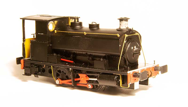
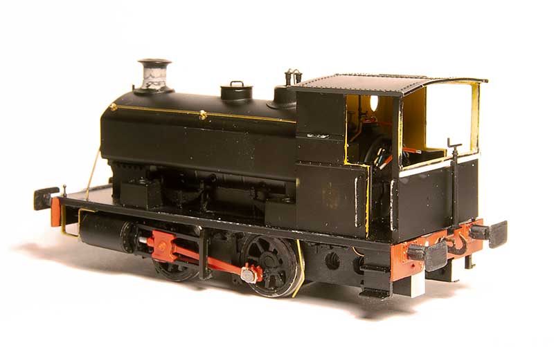
One of my slow burning projects has been a humble little 57xx tank. A combination of the old (But essentially quite good) Mainline body and a High Level Kits chassis but with a bit of twist.
Iain Rice wrote about these back in MRJ 61 and 62 using a similar route, in his case using a Perseverance chassis as that was what was available around the time, and I would urge readers to refer to this as a start point.
The High Level chassis
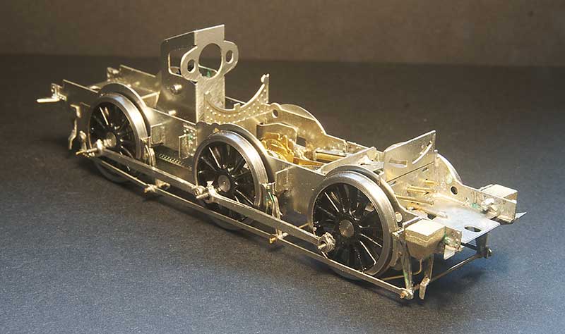 Like all of Chris’ chassis this was a joy to build (this is my 4th of his chassis kits now, who would have thought it?) I opted to use Brassmasters bearings which may have messed the alignment up a little as I found I needed to mount the break gear 1 mm lower than as supplied. Strangely though the buffer height seems fine. I differed a little bit from the instructions by making all of the brake gear removable. The rear rods that go behind the wheels seems to trap the rear axle in place as supplied.
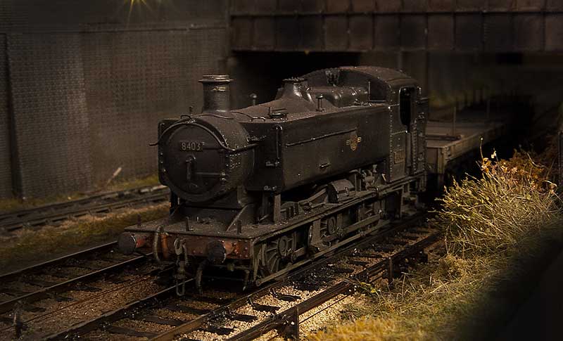
Eagle eyed viewers might spot something little odd and yes, you’ve guessed it – I’ve gone off piste again.
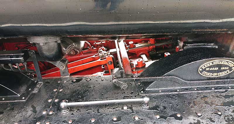
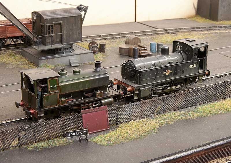
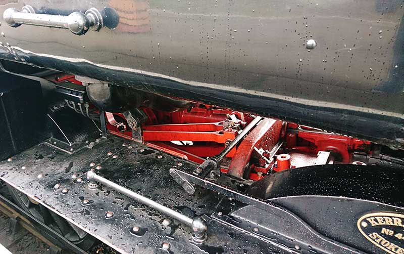 A couple of prototype pics from the Severn Valley. Personally i though the inside motion was pretty obvious looking at the real thing and while there is a representation of it in the High Level Kit I wanted it to move.
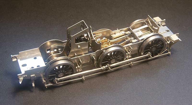 So this is a mish mash of bits – Brassmasters 4f bits at the axle end and Finney GW bits at the front. The GWR version of inside motion seems much simpler that the midland one and the hardest part of this task wasn’t putting it all together but getting it in place. Being a small loco theres not a huge amount of wiggle room.
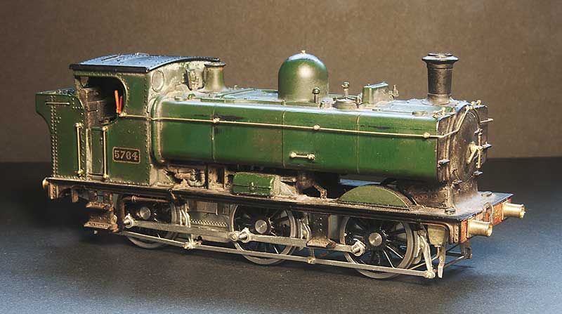
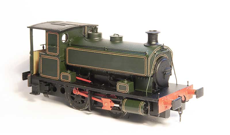
The body is essentially good, you could say extremely good for its time. The obvious stand out bit of weirdness was the top of the dome but nothing a spot of filing can’t sort out. It did come with a separate main handrail and some wire ones around the bunker but they were all a bit heavy so i replaced those along with those handrails that were moulded on. I reduced the size of the front wheel splasher by cutting it off and gluing it back on, The width of the cut being all you really need. I didn’t feel the need to fiddle with the centre and rear ones. While on my 94xx I replaced all the pipework under the tanks in front of the cab with this model I thought it was good enough as is, although I have cut away the ‘holes’ as per Iain’s article. Theres a bit more detailing to add to the footplate yet and the lower pipework will need to be replaced.
Latest building and what does it have to do with lions?
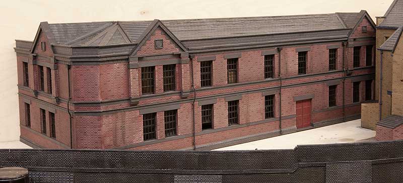
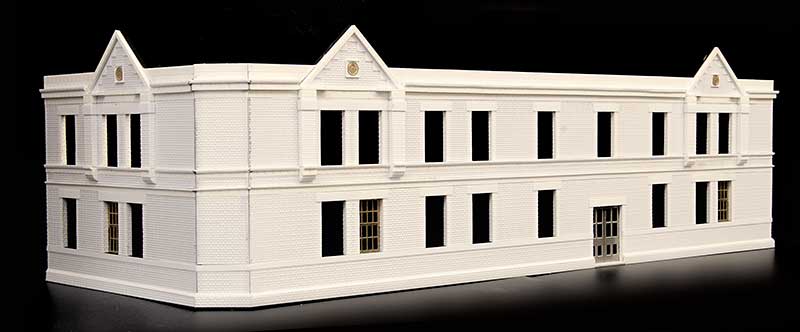
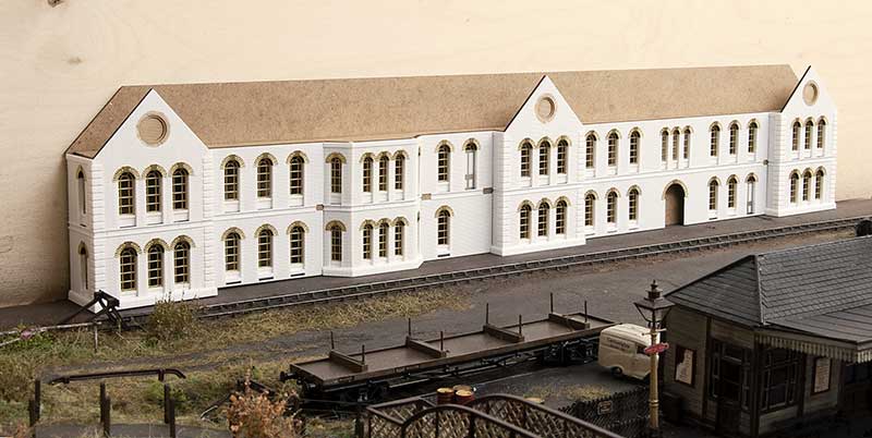
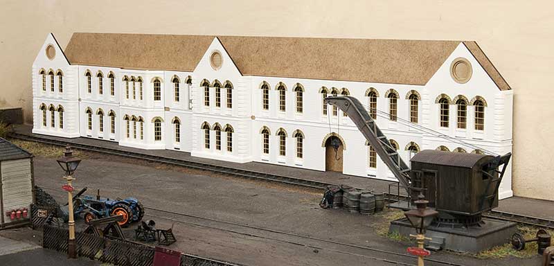
 This is my latest building for Brettell road and likely to be the last but one physical model building for the layout. I have plenty more buildings to create yet but as those will be on the backscene they will need to be illustrated instead.
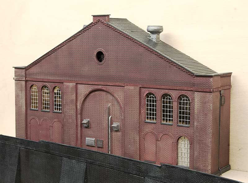
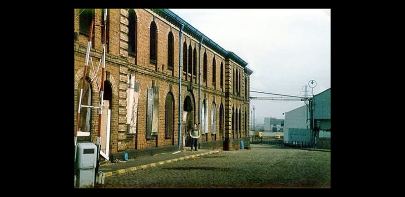
As usual it takes its inspiration from a local structure and this time its the Lion Health building in Stourbridge. Or at least a bit of it. Construction is the same as the others featured recently so I wont go over old ground again. Before it was a health centre the Lion Health building was an Ironworks built by Foster, Rastrick and Company in 1821. John Urpeth Rastrick was originally from Morpeth and had previously constructed an early railway locomotive for Richard Trevithick in 1808. The company would continue to produce steam engines as well as proving machines for chain cable, saws, mills, and boilers. It also produced structural components for buildings, bridges and gas works and in 1825 it listed railway components in a catalogue of products including rail, sleepers and chairs. Its fourth locomotive, Agenoria, was built for the Earl of Dudley’s railway and it survives to this day at the National Railway Museum. The company fared far worse than Agenoria and it was officially dissolved on 20 June 1831 and it was absorbed into the Stourbridge Iron Works of John Bradley & Co. James Foster was already the major partner (John Bradley was his half brother) and after 1832 James became the sole owner.
The site went through several more owners but they kept the name John Bradley & Co. (Stourbridge) Ltd. The first was when, in 1919, the Stourbridge Iron Works were sold to a company owned by Edward J. Taylor and then in the interwar period, N. Hingley & Sons Ltd took over but it still continued to trade under the John Bradley & Co name until 1963. The company was finally wound up in 1966 but the Stourbridge Ironworks continued as a rolling mill within the F.H. Lloyd Group until 1982. The building became derelict was nearly destroyed completely due to a fire in 2004. In 2012 it was renovated to become Lion Health which opened in 2014. In 2009 a couple of urban explorers managed to get in and took some pictures, these can be seen here.
What have lions got to do with any of this?
In 1829 Foster, Rastrick and Company built a locomotive for the Delaware & Hudson Canal Company in the USA and this loco, Lion, or rather the Stourbridge Lion is noted to be one of the first foreign built locomotives to be operated in the United States, and one of the first locomotives to ever operate outside Britain. The locomotive performed well in its first test in August 1829 but was found to be too heavy for the track and was never used for its intended purpose of hauling coal trains. Parts of this locomotive also survive and are on display at the B&O Railroad Museum in Baltimore.
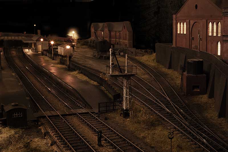
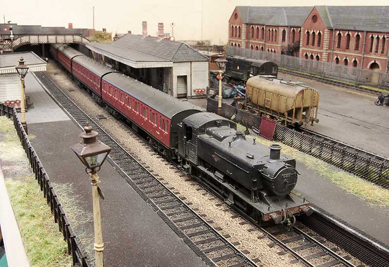
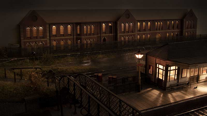
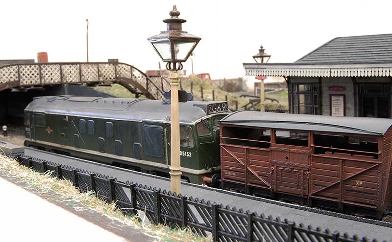
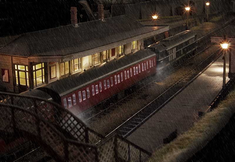
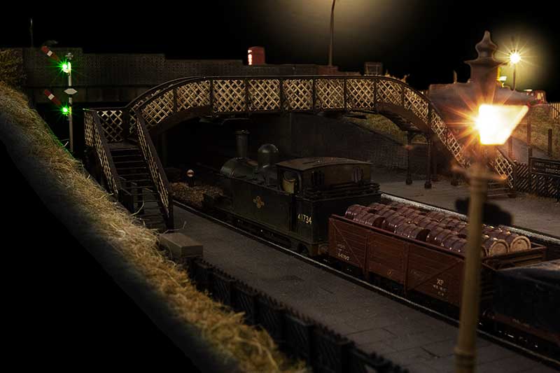
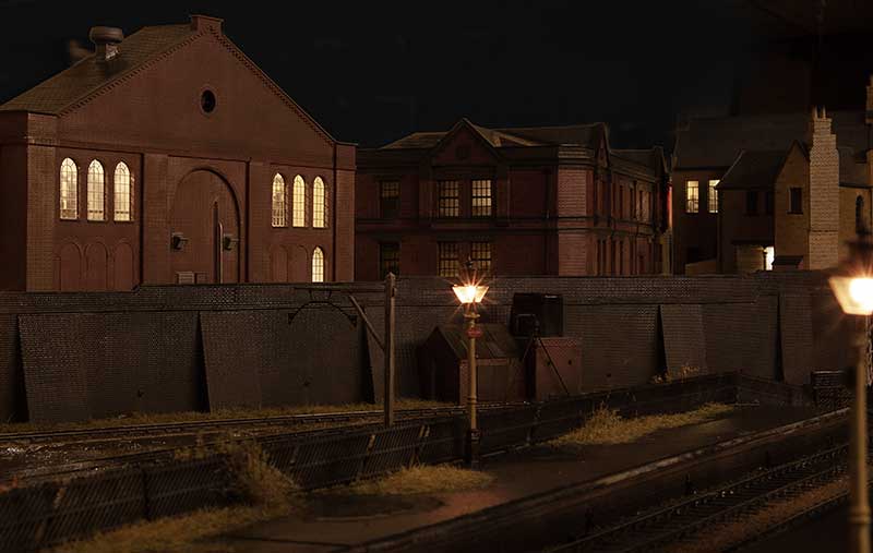 A view from the platform. I think i’ll tone the lighting down a bit more.
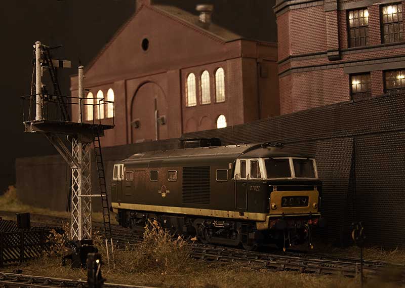 The recently completed Hymek trundles past.
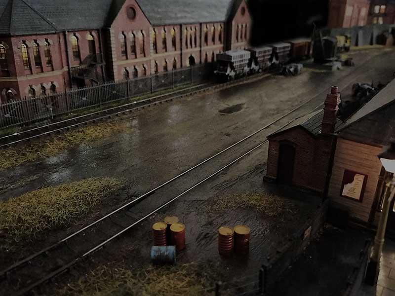
Below are a couple of overall layout shots which I think captures the wet look I’m after. The last one from my phone so apologies for the lack of depth of field.
Funny little Alien
For all of my lifetime, certainly my time aware of railways, mainline diesel locomotives have been powered by a diesel engine driving electric traction motors. However the Western region was never really one to follow what everyone else was doing and invested heavily in Diesel hydraulics. Of those the largest class and the only one to fit into the type 3 category were the Hymeks of which I missed out on. When I was born there were half a dozen still in service and they were withdrawn before I had transitioned from a 4 legged human to a 2 legged one. So they are all a bit alien really.
Apart from the transmission (and the idea of a mainline loco with gear changes) there were other things that were a bit odd. Why wasn’t the radiator fan housing central? Why didn’t they use no.1 and no.2 ends, Instead of having A and B and why was the radiator at the back not the front like everything else? Despite all the weirdness they were attractive little locos though so when a Heljan one popped up cheaply on Ebay (described as having intermittent running) I put in a cheeky bit and as no one else did, a Hydraulic is coming to Brettell Road. 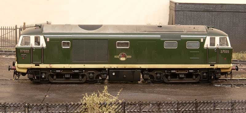 Not having any 00 track I didn’t investigate the reported running problems but the Heljan wheels were filthy and having swapped them out for some Alan Gibson ones no running issues were encountered. This model is one of Heljan’s early efforts and in terms of getting the shape right still one of their best. However there are a few tweaks that can be done. The roof horns were broken so they were replaced with Markits brass ones. The buffers were a bit naff so those were replaced with Lanarkshire Models ones. The numbers and builders plates are from Shawplan/Extreme etches. The rest is really down to working with what Heljan give you. The bodyside windows are flush glazed but not flush enough so they were cut out and remounted. The cab side and door windows are fine but I did add the droplight strips from 10×10 microstrip.
Not much to do on the chassis really – I added the mileometer on the leading axle of the B end (left) and I thought the pipework on the bogie frame at the A end was a little too fine so replaced it with wire.
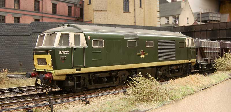 This is the A end from the other side. As I was doing an early batch loco I carefully cut off the headboard clips and touched in the yellow. The windscreens were also not flush enough but it was easier to just replace them with clear plastic cut to shape. Oddly the glazing on the headcode box (yes i know the headcode is wrong for the train) was too flush so this was replaced as well. Windscreen wipers are again from Shawplan and the brake pipes are from Hornby (the loco wasn’t supplied with any). I also remounted the tank under the bufferbeam and added a little pipework. To avoid confusion when it comes to DCC I’ve followed the diesel electric convention and set the fan end as forward.
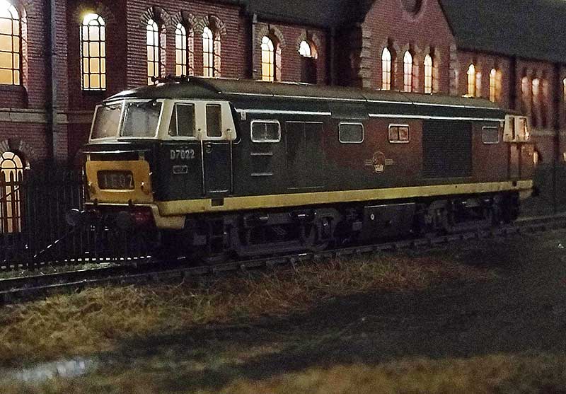
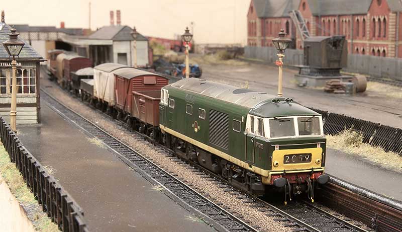 The model is weathered to look new but not 10 yards from the factory new. Im aiming for a few months and bear in mind the layout is set in autumn. There seems to be a tendency among modelers to weather Hydraulic locos to look an absolute state and most of them did end up that way in real life. So basically washes that I’ve pretty much cleaned off again as best I can before light dustings of track colour and roof dirt. This was followed with streaks from AK interactive spilt fuel and grease before finally the obligatory rain effect. Diesel locos tend to have characteristic weathering which is unique to each class (something which a lot of professionally weathered locos you see seem utterly devoid of). Class 24 to 27 have the water stain from the roof, just inboard of the fan. Class 50s have 3 leaks that run down the fuel tanks, class 20s have an odd direction for the staining deposits from the exhaust and class 31s have the oil leaks through the bodyside at floor level. Hymeks have this too but not as much and from my research only later in their (short) lives. They do however have a distinctive leak on the fuel tanks and this seemed to have been from new.
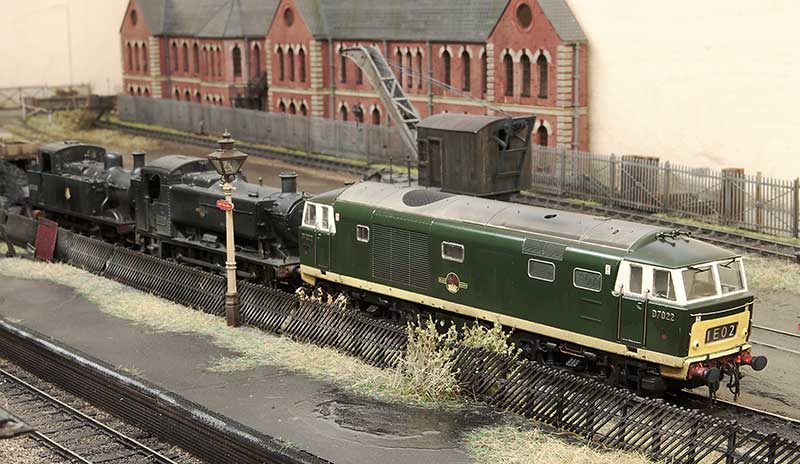 Any reason for D7022? Ive always had an affinity for the Lickey incline and these 3 locos were all regulars on banking duties over the years. The Hymeks went there much later than Brettell Road is set and were the second class of diesel to work the incline. The first being English Electric type 3s (class 37). A lot of Hymeks worked the Lickey but the initial ones were D7021-D7025. In his book, A life on the Lickey, Pat Wallace talks about them and mentioned that early on they preferred to have the A end facing north (up the gradient). If a loco turned up the wrong way round it was sent to Worcester to be turned on the triangle. He doesn’t give any detail on why this was the case but you could lock out first gear in a Hymek and the equipment cabinet for this was in the A end. The locos definitely had first gear locked out while on this duty. This was because the change from first to second gear was right in the range where trains were banked and they could snatch. The Hymeks having only one engine were a little worse for this than the Warships and Westerns.
One little anecdote Pat also mentions concerns the 17th January 1968 when a kitten was discovered in the engine room of D7025. He was adopted and named Hymek (of course). He crops up again 10 days later when he had managed to hide himself in the bogie of D7022 and refused to come out. It was reported that Hymek the kitten did 4 trips up the Lickey!
Stretching things out a bit.
One aspect of making Brettell Road longer is that the original fiddleyards will need to be replaced. As such the opportunity will be taken to increase their length from four feet to five which means I can increase the cassettes from three feet long to four and a half. Any bigger than that and cassettes start to become unpractical and a bit sketchy anyway.
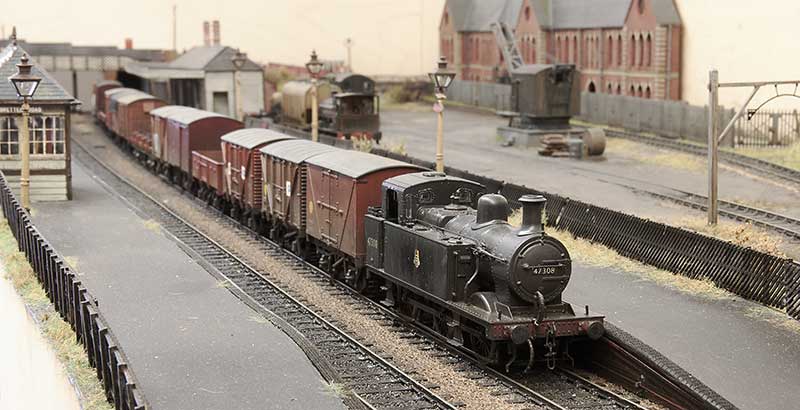 A four and a half feet long freight train on Brettell road.
 A four coach passenger train. When I built this originally one of the (then 3 coaches) wasn’t finished as I hadn’t detailed up the underframe yet and just swapped the bogies. This was due to Brettell Road’s first outing coming up (Scaleforum 2018) and it never got moved from the ’roundtuit’ list since.
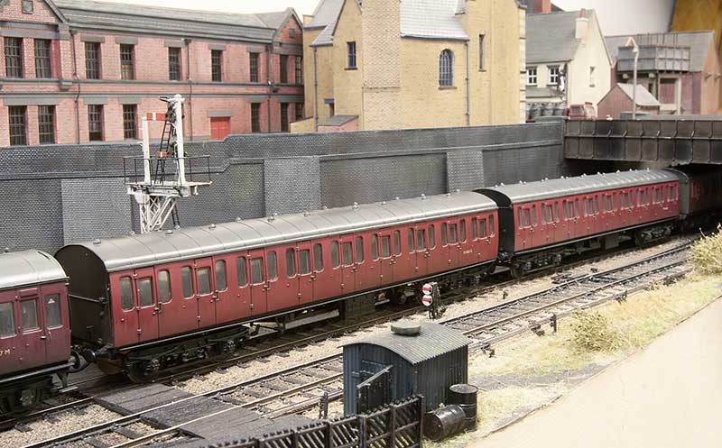 But when another cheap coach popped up I decided to get this little train ticked off so they were both detailed up together. Leaving just one thing outstanding…
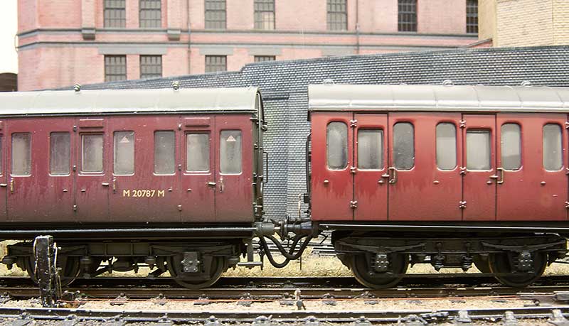 …the brake pipes. I admit to not using working ones on my wagons, as the layout is principally a shunting one, but as this is a fixed rake of coaches why not? I came up with the original idea for this back around 2005 and articles appeared in update and MRJ. The original update article can be downloaded from here. Where I have differed from my original article is to have one long pipe for the vac pipe and another long pipe for the steam heat pipe I figured 4 short pipes would just stick together in a clump! So theres a magnet on the end of the pipe that connects to a magnet in the bufferbeam. All simple stuff really but it does mean that the coaches and their pipes have to be couple up or the pipe will drag on the track and no doubt get stuck!
Tired of tiles!
After working my way through a lot of laser cut strips of tiles I can call my building(s) project effectively done. 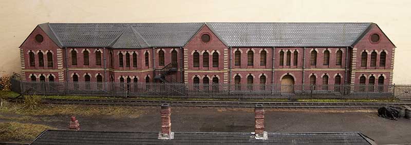 There are several schools of thought when it comes to what to do with low relief buildings. The easiest is to keep them parallel to the backscene however if you don’t (as I haven’t) then the roof can actually become a little bit of a problem area. Theres 2 main ways to address this, Keep the pitch of the roof the same and cut the top at an angle. Or keep the top parallel to the rest of the building and adjust the pitch. My personal opinion is that the latter is the better option. The pitch on my acorn building is significantly different from the left end to the right end. One advantage of using tile strips over embossed plasticard is you can adjust the rows to compensate for this and hopefully no one will notice what trickery you’ve been up to!
 The same applies to this building although it’s not quite as dramatic.
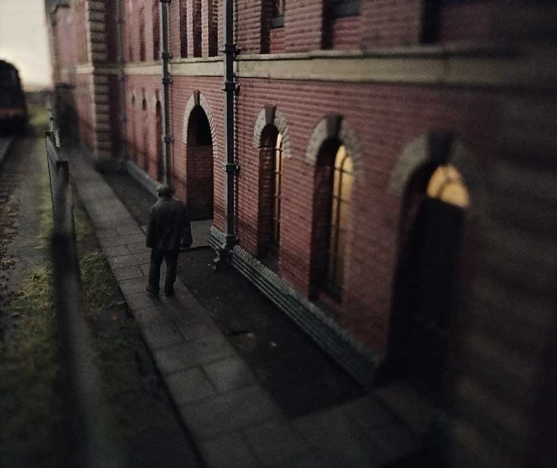
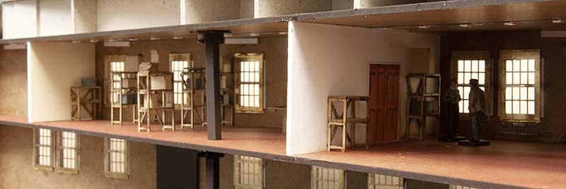 The thing with lighting buildings is they look a bit weird if they are just empty boxes. I don’t feel you need to model everything inside though, just enough clutter to give a hint of something inside. The shelving and cardboard boxes are from scale model scenery. I have found its something people at shows to look for and I think is nice to have some little ‘treasures’ that people can discover for themselves.
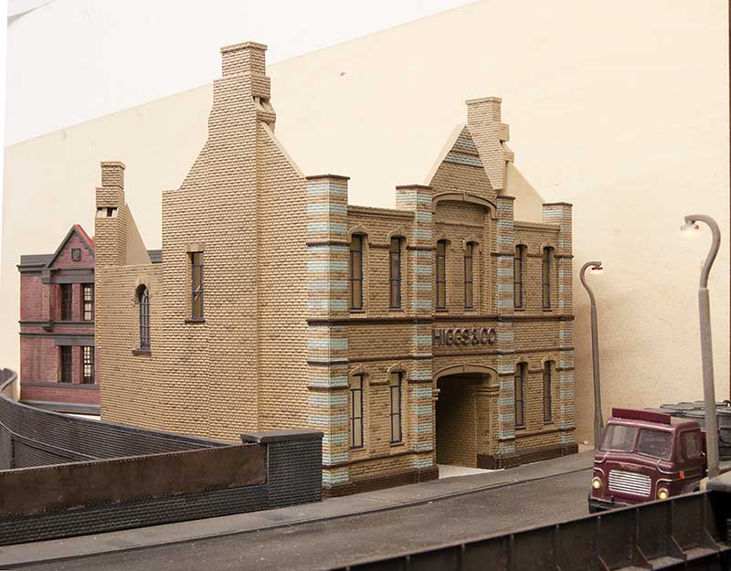
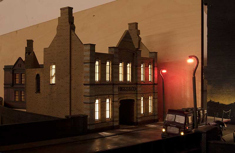
 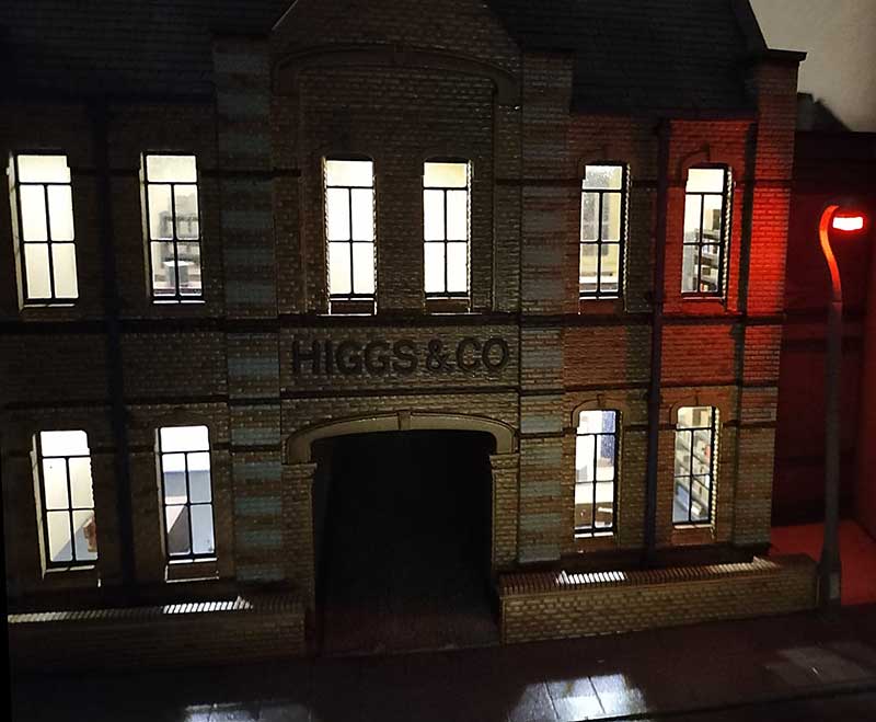 The Higgs and Co. building also has some ‘officey’ clutter. In the late 50s offices seemed to be laid out more like a school classroom than the more ergonomic arrangement we see now.
 The roof of the rear of the Higgs building has some weird shapes that were a bit of a faff to work out if I’m honest.
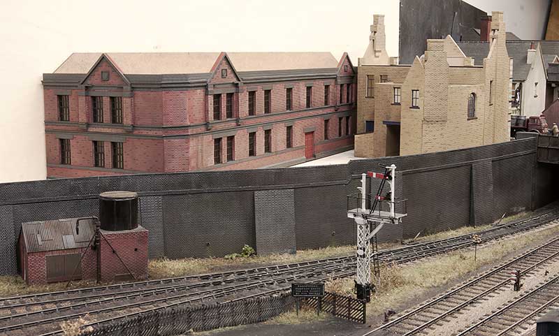
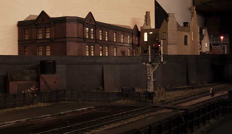
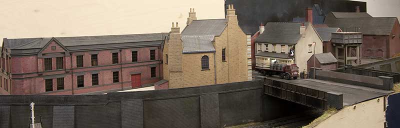 I do feel that the middle of the layout has a suitable black country-ish feel to it now.
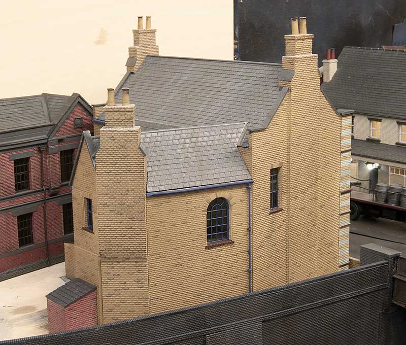
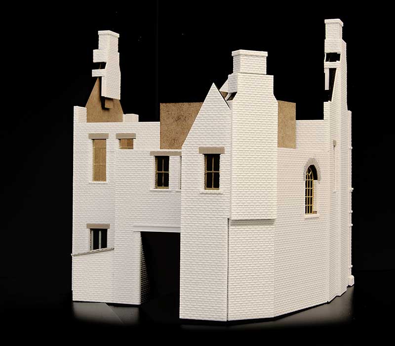
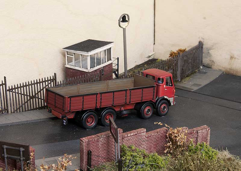
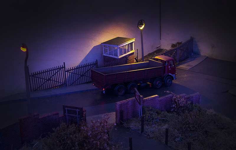
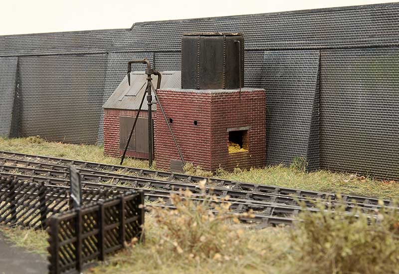
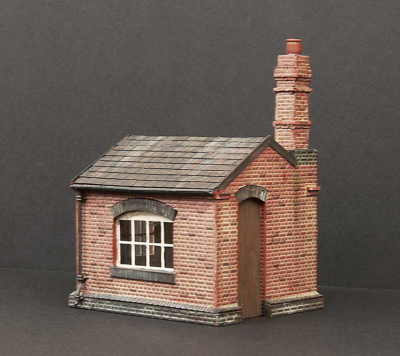 One little building I bunged together is this little weighbridge that will sit behind the main station building. Its based on the one at Wombourne (See here) and I was initially attracted to its over the top chimney and the way its just stuck in a corner. I did have to reel my enthusiasm in a little as the chimney at Wombourne matches the station so to model it exactly as it was when the ones on my station don’t look anything like, would have been a little weird.
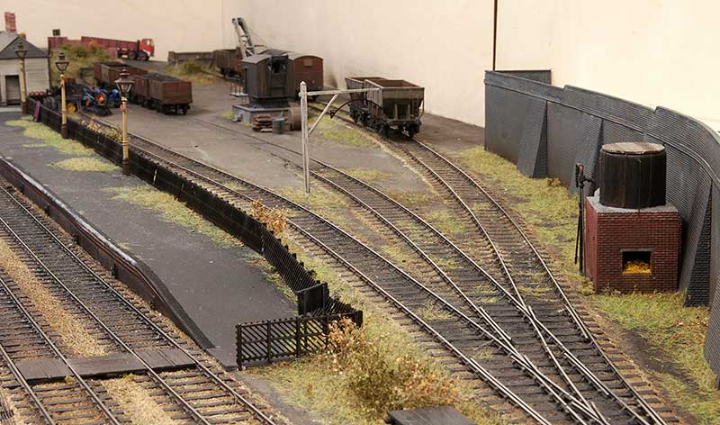
Below a few pictures, I feel the last one really captures the feel I want for the layout.
building boom – now painting boom
Ive been busy painting. Not a huge amount to say really so I will let the images do the talking. Next will be roofs and tiling. Lots and lots of tiling!
Building boom
In an attempt to keep some momentum going I’ve been doing more building work. This time for the right hand end of the new bit.
 This building is based roughly on the office building from Birmingham central goods. Same method as before but this time using Brassmasters etched windows.
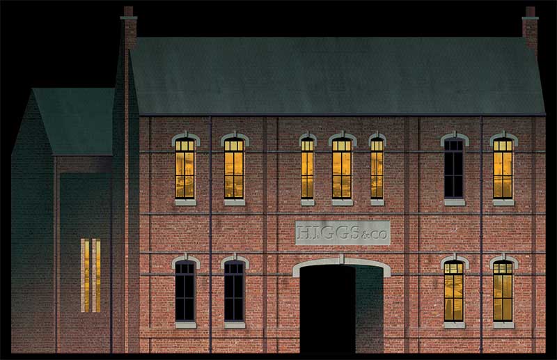 Originally the area in question was the end backscene of the original layout and this drawing was based very loosely on the Harris and Pearson building on the real Brettell Lane (see here for more info). The original basic drawing was modified and sent to Tim to be turned into an MDF carcass.
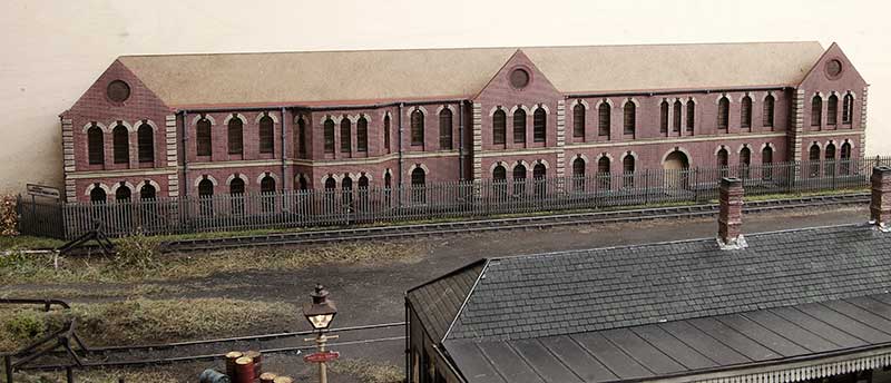
 And here is the result so far. Windows are a combination of my own and Brassmasters etches.
 This is the much less ornate but somehow at least as interesting rear view.
 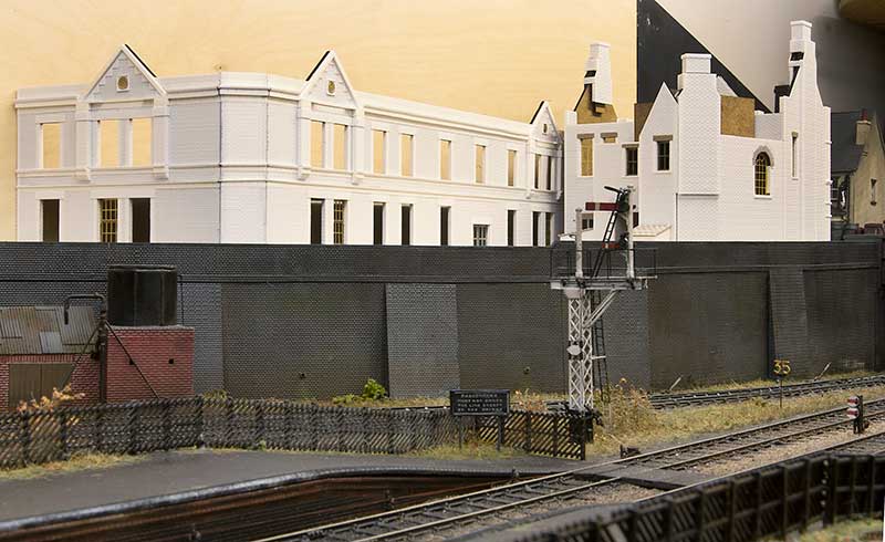 A rough idea of where it all goes.
From Little Acorns, Part 2
 Work continues on my latest building. Gutters are from Modelu. When I last used Modelu guttering I found getting it stuck on was quite problematic however this time I tried Ultraglue from MIG (which I’ve mentioned here before) and I am pleased to report it works very well.
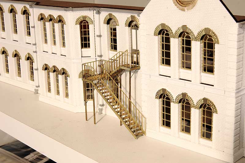 Fire escape from Langley Models. A few people noticed the upper door in my last post.
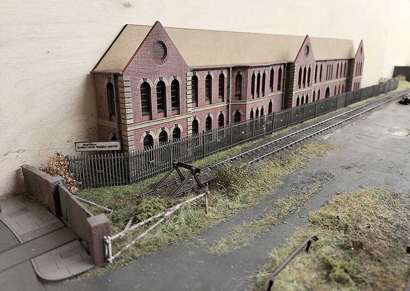
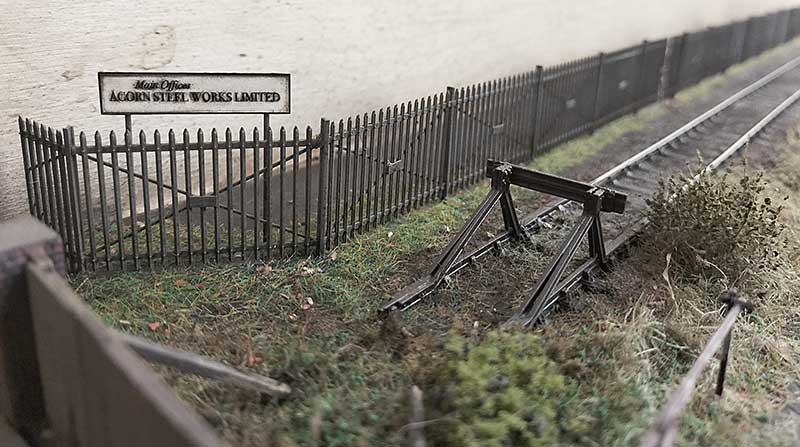 I’ve started to work on the base for the building to sit. The fence is Knightwing security fencing modified to resemble that seen in pictures of the real Round Oak. The sign was part of the etch I drew up for the building windows. I decided not to call it Round Oak as its not a model of the real place but Acorn Steel works had a nice ring to it as its smaller. Acorn was the name of the company magazine issued at Round Oak.
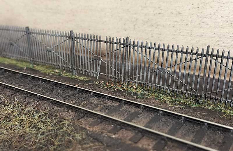 Moving along the fence we find an area where someone has made a hole! Perhaps it was kids trying to get in or perhaps it was a worker looking for a short cut to the station?
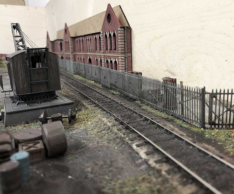
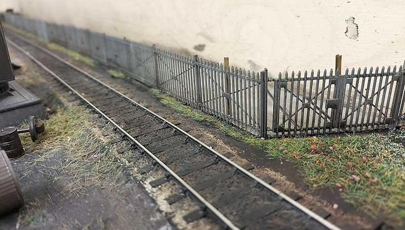 The other end. I decided some remnants of an internal line into the works would be an Idea. For the surface behind i have tried out some AK interactive concrete. Theres areas of the building that will need to be concrete or stone however the texture is too heavy for 4mm scale. It would work as very, very rough concrete or as a base for rough ground perhaps. In this case I sanded it pretty much flat.
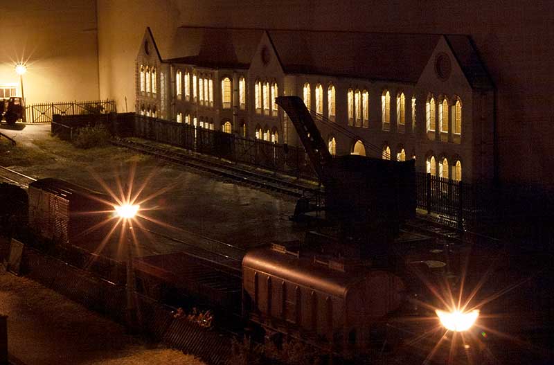 Finally I couldn’t resist a little test run of the buildings lighting.
Another wagon diverson
Breaking away from the current building works for a moment a little wagon based diversion. As per normal mundane stuff with a few little bits of tweaking that most people will likely never notice.
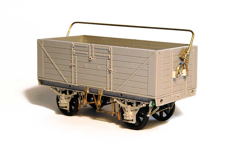
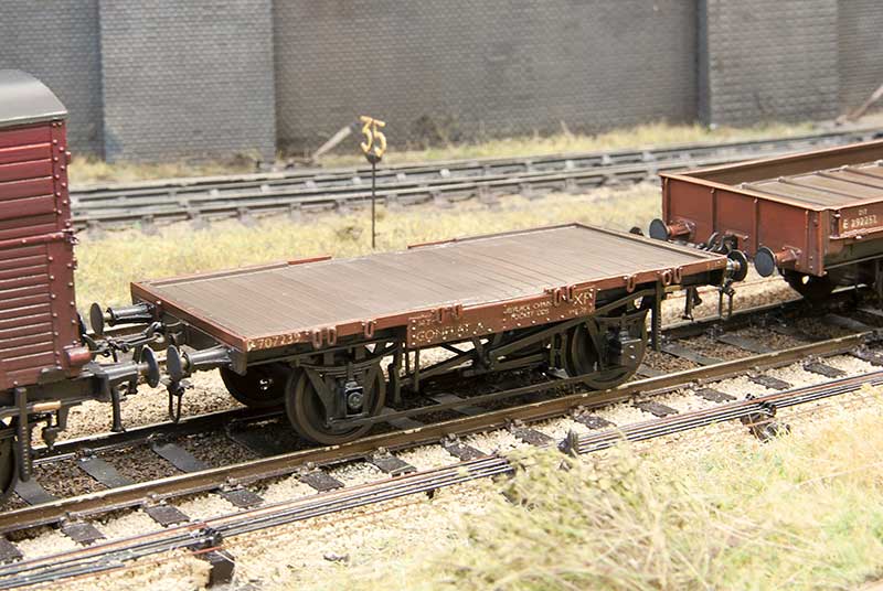 Conflat A from the Parkside kit. As per the last time I built some of these I beefed up the links a bit as I thought they were far too subtle. I fancied an empty one for a change and also added a missing (yeah sounds a bit weird that doesn’t it?) axlebox cover.
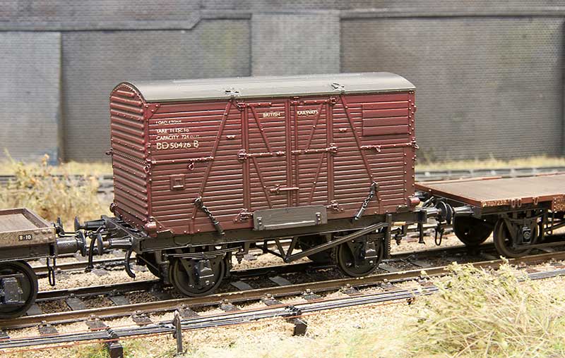 Next up an LMS diagram 1838 container flat. Built from the parkside fitted LMS chassis kit with extra bits and bobs.
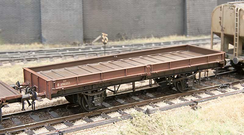
Finally an eastern region plate. When i did my fish van a few posts ago someone on the clearing house facebook group (highly recommended if you are on facebook and like wagon building) pondered if the chassis could be used to do an eastern region plate. Personally i thought it easier to go with the supplied chassis and replace the brake gear. Another Parkside kit.
From Little Acorns, Part 1
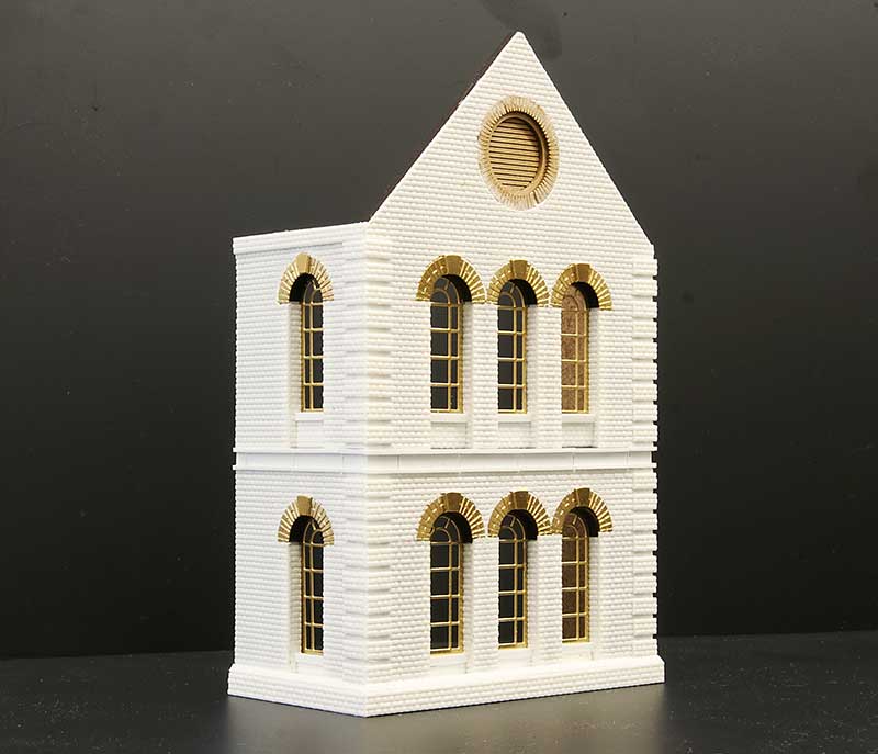
Construction has started on the latest building for Brettell Road. I’ve tried to incorporate some lessons learned from the previous efforts.
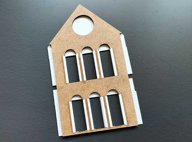 The main lesson being to do something more robust with the corners as these have been slightly problematic in the past. I decided to laser cut the main carcass and overlay it with plasticard. It may have been easier in the long run to laser cut everything but I like working with plasticard and scalpels and i didn’t fancy a huge session on my computer drawing bricks. As usual Tim kindly did the cutting for me. As you can see from the picture I’ve cut recesses in the corners and mounted some evergreen strip to give something solid for the overlays to stick too. It’s early days but it seems very solid so far.
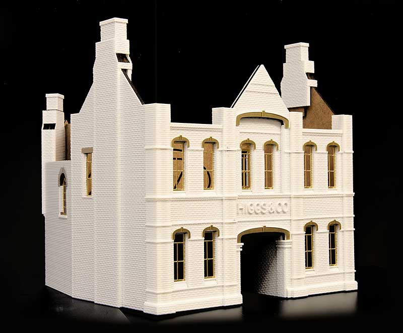
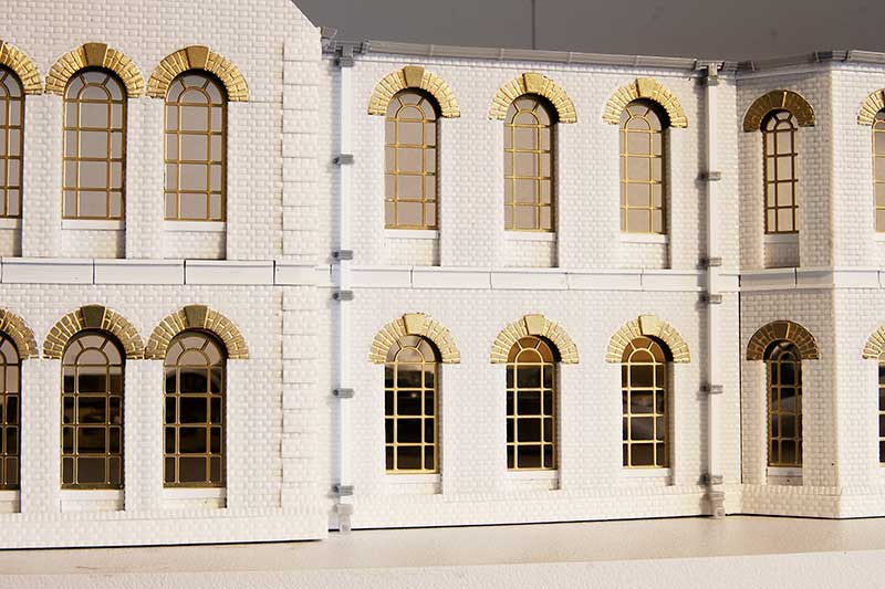
 Turning the part around and moving on a bit, this is the front. Ive built this in a kind of modular way. I drew up the windows and arches and had them etched. There are 3 of these sections required for the building.
 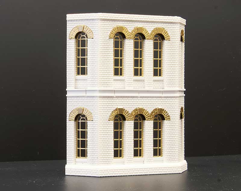 This is another section. Ive used the admin building from Round Oak as my inspiration but moved things around and adjusted them to suit. It’s an ‘inspired by’ model rather than an exact replica. This section was on a different face to the one I am modelling as it overlooked Dudley Road.
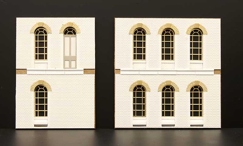 To join these bits together are some flat wall sections. These are the smaller ones. Ive missed some bits off at this stage as I figured it would be easier to add them once its all together.
 And the larger one.
 I didn’t manage to find a huge number of images of the real building. Theres one in Ned Williams book on Brierley hill and this one that my friend Frank Collins sent me. Sadly Frank passed away very recently and I missed showing him how I was getting on by only a month or so. I sincerely hope he would approve of my efforts. The model will be dedicated to him.
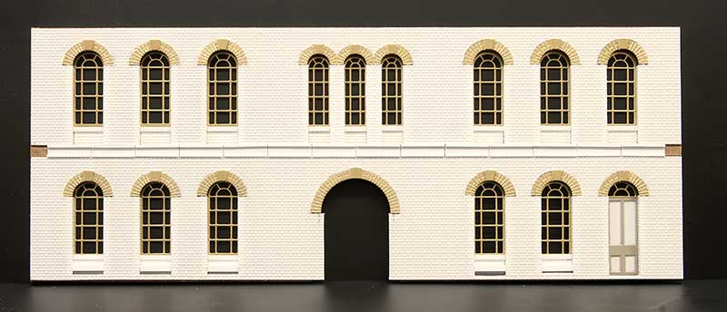
 Progress so far roughly plonked in position.
 And from the other end. Much still to do!
Low cost modelling
 I was pleased to find that given the recent high temperatures and the layout living in a shed, that there appears to be no ill effects and all the rails are still straight and pointing in the right direction. I hope everyone reading this can say similar.
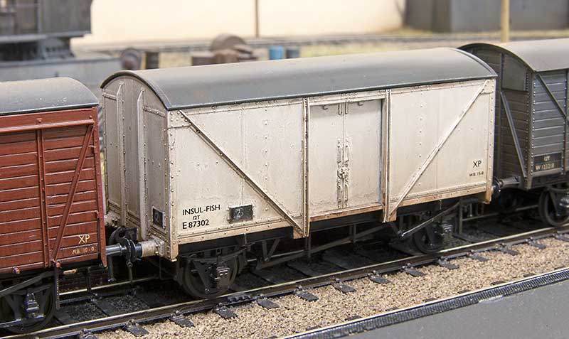
The above is a major blast from the past. Years ago when the West Midlands Area Group of the Scalefour Society was active, its organiser, Les, one week supplied us all with a parkside fish van kit. I think (memory is fuzzy if I’m honest) the idea was some sort of little competition to see what we would do with it. I don’t recall that anyone did but since then its sat in my kit stash contemplating its place in the world. As you can see it’s finally been built. I must admit the very long wheelbase produces a pretty ugly proportioned vehicle but its ready for service on Brettell Road. A note of thanks to Andy Hanson for kindly supplying the transfers.
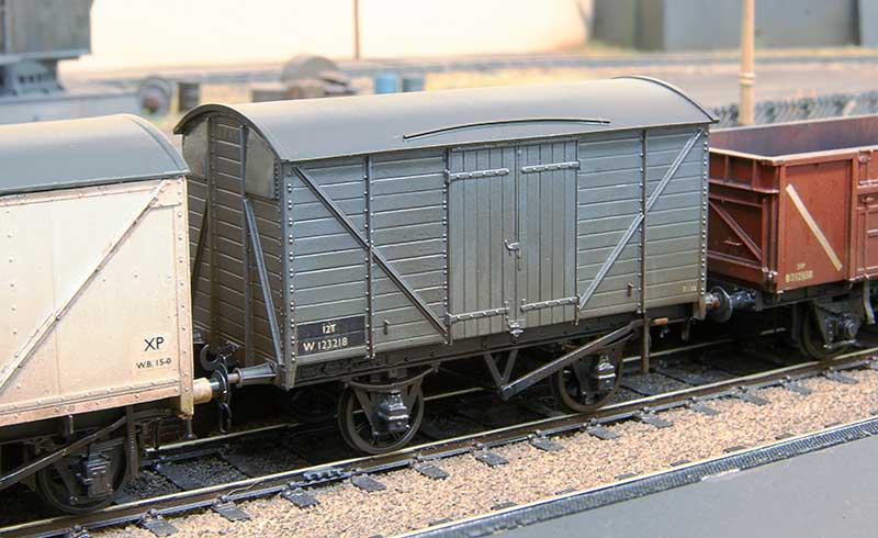 Above is a V33 van again from my spares box. It uses Ratio sides and a Cambrian 9ft wheelbase underframe. I don’t know how I ended up with the sides and while all the bits had, obviously, been paid for at some point I’m calling this one a freebie!
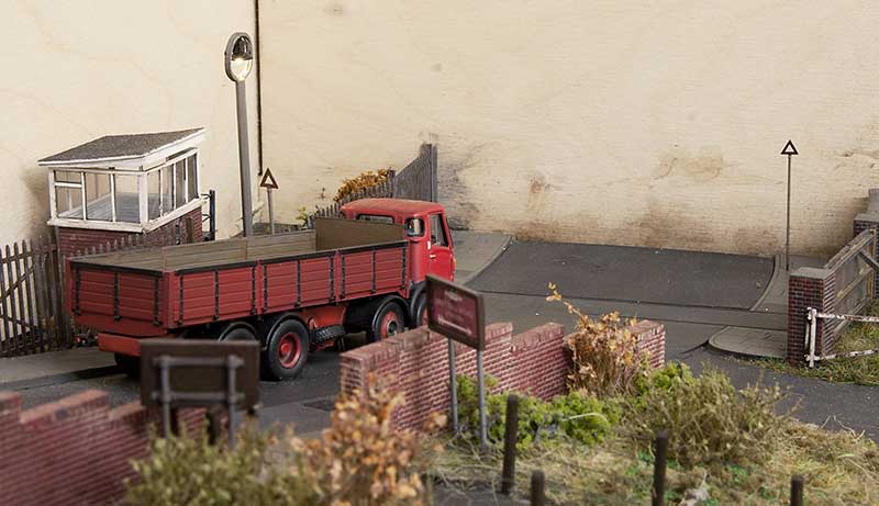 Added a couple of pre-Worboys road signs from Shirescenes. These are inspired by a picture of a Barclay tank crossing Level Street that I found. I made the furthest one about 80% the size of the nearer one to force the perspective a little.
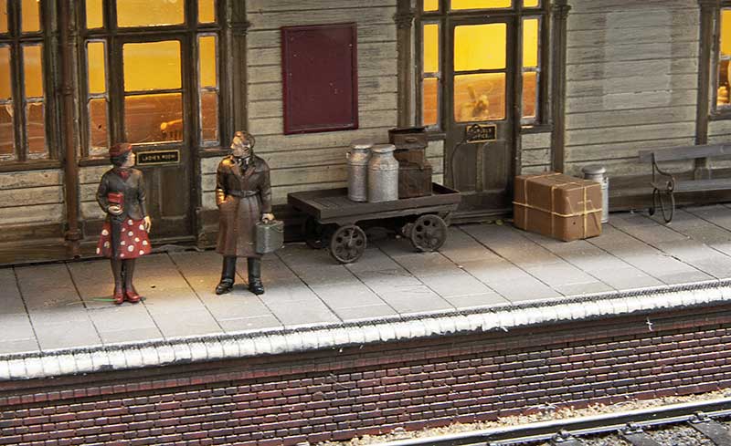 Finally a couple of milk churns from Modelu. To get the galvanised effect I painted them silver. Then a very light dusting of Halfords grey primer (holding the churn at arms length from the spray can) followed by matt varnish. I think it worked but if anyone will ever notice, who knows?
LMS long tube
Just missing out on my last post is this model
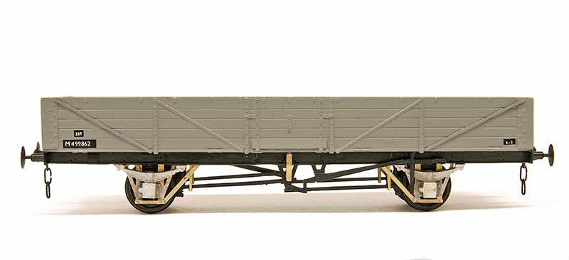
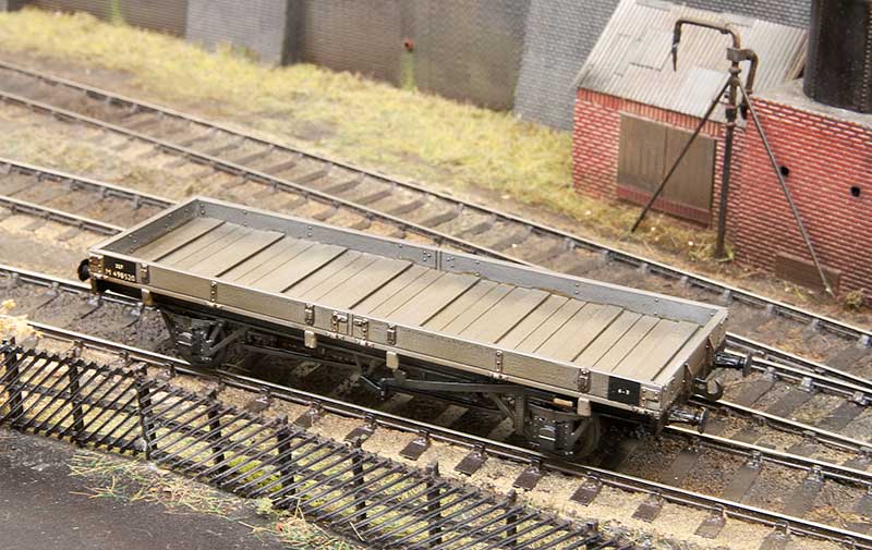
An LMS diagram 1945 Long tube. It uses a Parkside BR tube kit which has been shortened to 30ft 6in over the body (122mm) and 17ft 6in wheelbase (70mm). The corrugated metal ends have been replaced with planked ones from plasticard.
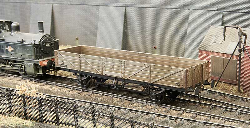
 A bit of a family tree starting at the top with an old Ian Kirk kit for the diagram 1675 wagon. The wheelbase for the top 2 are the same.
 Just a couple of pics for the hell of it!
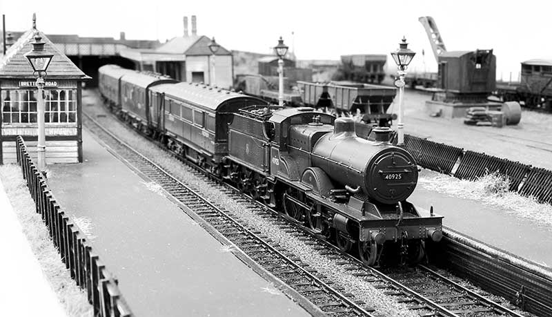
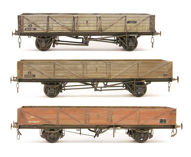
A Parkside quartet.
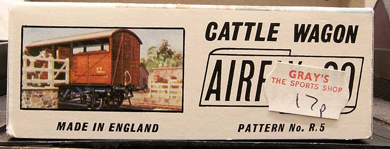
 The Airfix meat van I did a short while ago has peaked my interest just a smidge. There is a little bit of local interest for this (or a well sketchy excuse for me to go waffling on for a minute or two!).
Meat products moved by rail were probably most famous for the Palethorpes vans that operated out of the Dudley area but Brierley Hill was also famous for another processed meat producer, Marsh and Baxter. Founder, Alfred Marsh brought a pork butchers shop (with slaughter house) from E.J. Smart on Brierley Hill High Street in 1867 and initially started out curing ham and manufacturing sausages. By 1912 he brought the A.R Baxter factory in Dale End, Birmingham. Alfred Marsh died in 1918 and the business passed to his son Alfred Edward Marsh. After WW1 the company continued absorbing smaller firms and was eventually granted a Royal Warrant for its York Hams, which they supplied to Harrods.
In 1927 They began using their own siding at Brierley Hill Station and at their peak employed some 1500 workers and slaughtering approximately 2000 pigs per day. It was quite famous locally for an advert featuring a pig pulling a trailer loaded with sausages and the strap line ‘Drawing his on conclusion’. In 1954 a modern office building was built on Church Street, Brierley Hill which being slighter higher than the Round Oak steel works did tend to dominate the town somewhat. They also took a keen interest in investing in and promoting local sports and social interests and had both a cricket and football teams (both mens and womens).
In 1962 the company was brought out by Falstock Marketing Corporation although the Marsh and Baxter name was retained. It would survive another 16 years until December 1978 when the company was closed.
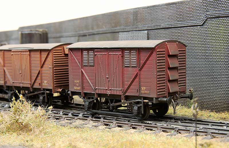
 This one is a Diagram 1/250 example using Airfix ends kindly supplied by my friend Ian. Knowing what I know now it would have been better to use a parkside standard 12t van as the meat van has different doors. Luckily I still had some suitable doors in my spares box. The ens needed chamfering to 45 degrees to match the ends and the floor needed shortening a little as the Airfix ends are thicker. I also used some spare underframe mouldings to get the BR welded plate fronted axle boxes.
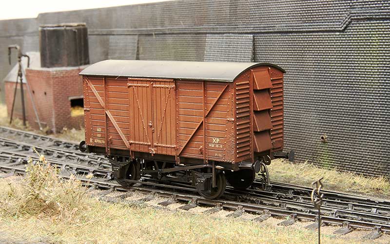
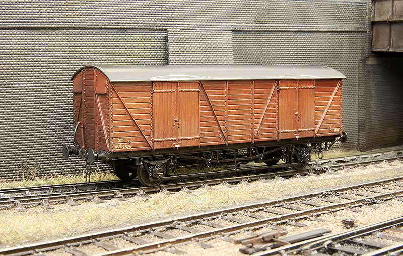 On the subject of vans I quite like these ex GWR mink Gs. Another Parkside kit with Bill Bedford springing and some other etched bits and bobs to refine the underframe a little.
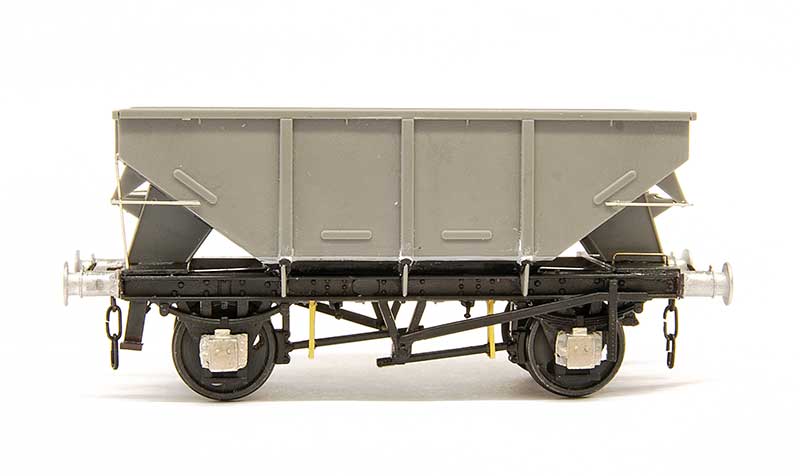 Moving on to Parkside’s latest effort. The BR 13t hopper. You can feel the Peco in this one! The underframe has similar feel (both in the way it’s done and the plastic its done in) to the old wonderful wagons tank kits. I needed to get the scalpel out to get it to fit together the way it was intended but once done it does result in a pretty solid chassis. I don’t know what happened with the supplied axleboxes but they seemed unfinished to me, almost as if there should have been an overlay as per the palvan kit. As there wasn’t I cut them off completely and replaced them with Wizard Models castings.
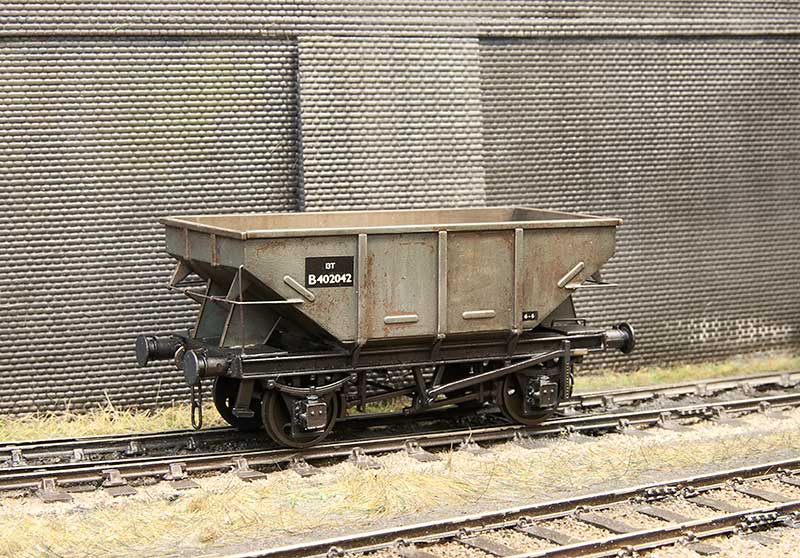 Knowing what to look out for it does build into a nice looking wagon and its pretty quick to bung one together. The model features some nice moulding on both sides of the hopper doors but with no where to really put any decent amount of weight I suspect many (like i will) will run them loaded.
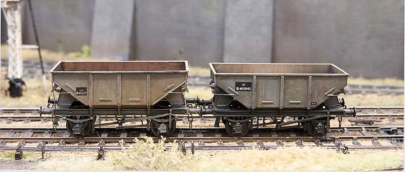 The inevitable comparison with my previous model from the Dave Bradwell kit. Draw your own conclusions.
Another classic
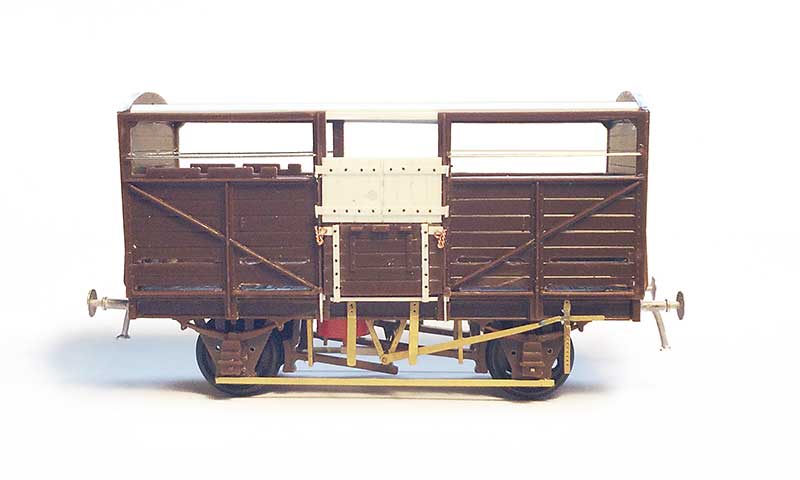 The good old Airfix cattle van. When I was a kid my dad built one of these so I decided Brettell lane should probably have one too. I deleted the opening doors (it was easier to replace the top ones completely than modify what was in the kit) and detailed the underframe with Mainly Trains, Bill Bedford and Rumney models parts.
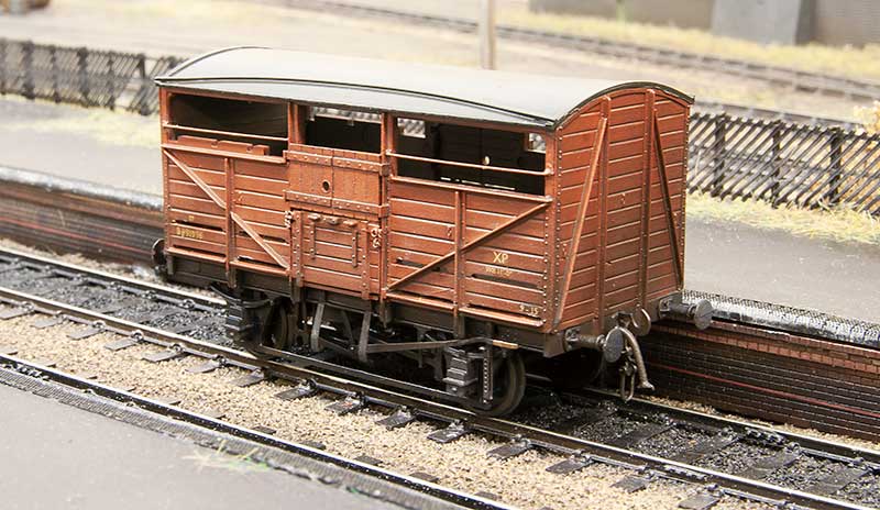 As with all Airfix kits of the time the roof was pretty clunky so that was replaced with a new one from 30thou plasticard and microstrip.
 Ive no idea when this kit was first sold but even with modern eyes this looks like it was bit of a bargain!
 Moving on to a more recent kit. The Chivers model for an LMS long low thats been in my stash for a few years now.
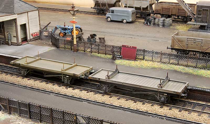 Also from Chivers, and also from my stash, I’ve finished off another LMS twin bolster. Chivers kits seem to have quite chunky underframe mouldings and while this isn’t noticeable on most of their kits I’ve built it was kind of more obvious on the first twin bolster I built (on the left). Potentially the use of sprung suspension adding to the problem I felt the underframe looked too wide and the w irons were too far from the wheels, giving a kind of 00 look to the wagon. On the new one (and the long low pictured above) I thinned the w irons to about half thickness and I’m happier now. It might very well that its only something I notice though!
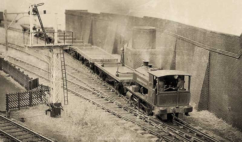 A ‘historic’ photo of the Barclay tank shuffling a steel train.
A couple of stragglers
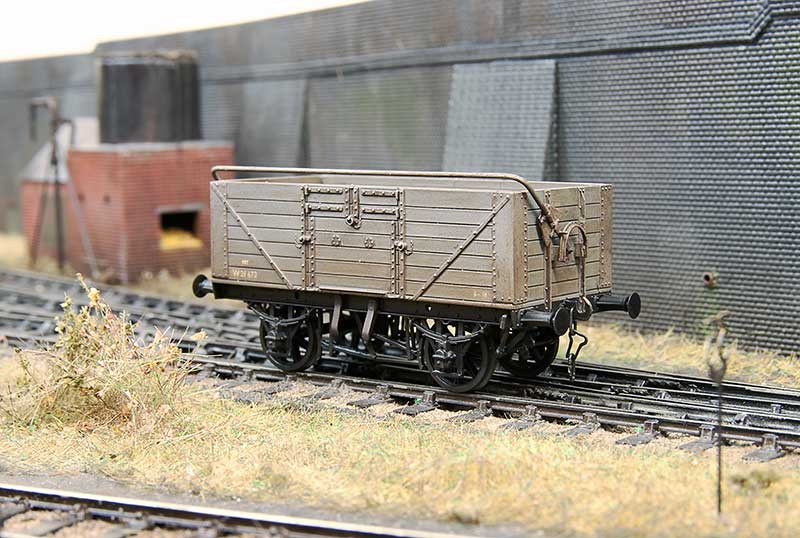
 Pictured above is a Cooper Craft kit for a GWR diagram 02 open wagon. I found that if you use the bearing holes supplied in the kit the wagon sits too high so the holes were enlarged vertically a bit at a time, checking the wagon on a bit of glass to ensure all 4 wheels stayed square. The rail is a modified Rumney models kit and the brake gear from MRD.
 The infamous Airfix meat van. Quite why Airfix picked this and not a standard 12 ton van is anyones guess. I replaced the gimmicky opening doors and the underframe with Parkside bits from my spares box. The transfers were cobbled together from what I had and those that were white were painted with revel clear yellow (730). Buffers on this and the GWR open were from Accurascale. Basically cheap and cheerful!
 A private railway favourite and an exhibition last hour staple, the good old brake van special! I think i might have overdone it a bit!
Bit of pick ‘n’ mix
Bit of a pick ‘n’ mix post this one.
 Lady Margaret now has her identity thanks to some custom nameplates from Narrow Planet
Finding your own compromise
When it comes to plastic kit building it helps if you think of a line. At one end of the line you have the kit as supplied, built as per the instructions with no attention or research what so ever on the prototype itself. At the other end you have the kit, researched, wrong parts replaced or corrected and superior parts substituted, as much extra detail as you can manage. Rumney chassis kind of thing. Inevitably we all need to find our place somewhere along the line that we feel comfortable.
This place can be influenced by several factors.
Cost – adding a lot of extra parts can mount up to quite an expensive model.
Expediency – high end models take a lot longer to build. Do we have the time
Reliability – no point adding every little detail if in use you’re going to knock it all off again.
Usage – if you wagon is part of a train of 30 that are only ever going to trundle past at a scale 40mph are you going to have the opportunity to notice the extra work?
Consistency – no point mixing highly detailed and basic kit builds together really.
Volume – how many models are we going to need?
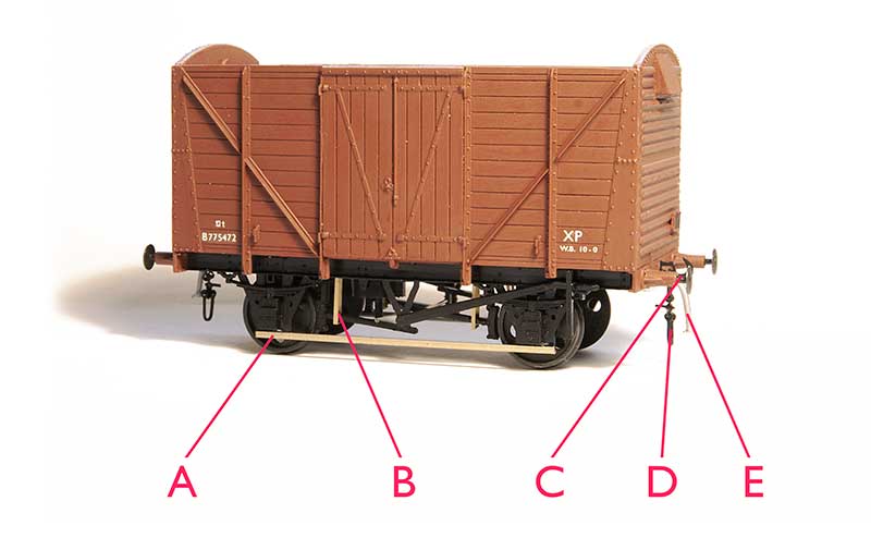 Heres my pretty much standard position along that line. The base model is a parkside kit. As mentioned elsewhere I’m not particularly worried about compensation or springing on a 10ft wheelbase wagon but i do use it for vehicles longer than 12ft wb.
A – brass tie bars. I use 0.8mm L section. the real things aren’t L section but i use this for strength and you cant tell unless you turn the model upside down. In plastic kits the tie bars are a real weakness ad they are either bendy, get broken or to avoid those 2 things, massively thick.
B – break hangers from Bill Bedford – It doesnt take much to add a little finesse to the brake gear and trick the mind into thinking its all a bit more refined that it actually is.
C – metal buffers, or in this case metal buffer heads. Unless your kit comes with metal buffers already lets be honest here, the plastic ones are going to be awful. These are MJT buffer heads.
D – couplings. A whole discussion on compromises in itself. In my case I use Smiths which i know are overscale but they are (quite) easy to use in operation.
E – brake pipe from Lanarkshire models.
Glue
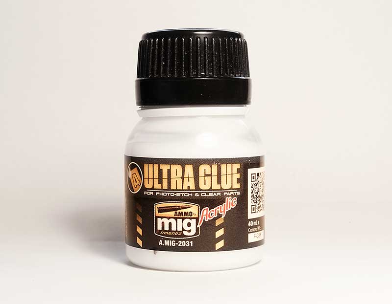 Ive recently been trying this stuff. Ultra Glue from MIG for etched and clear parts. Its water based so can be thinned if required and so far it seems to do the job at least as well as superglue. Its especially good for fitting name plates as while it has good grab it takes a few hours to fully harden and being water base any that creeps out can be lifted off with a wet paintbrush.
Reading
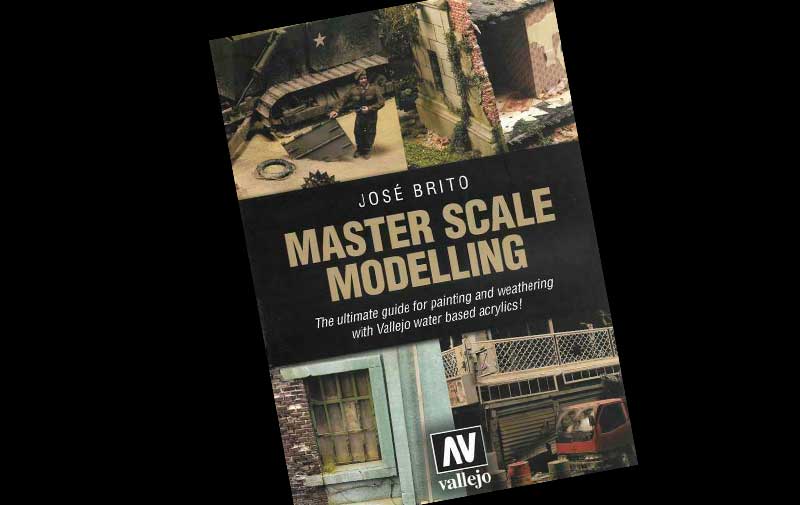
It’s been an awful long time since Martin Welch treated us to his ‘bible’ the art of weathering. And while still essential reading things have moved on a bit, especially so in the last few years or so. Some of the paints Martin used are no longer available (Humbrol tarmac for example) but theres a whole market now of weathering paints and materials. This (rather large at over 500 pages) book is an excellent window outside of our sometimes a little comfortable railway world.
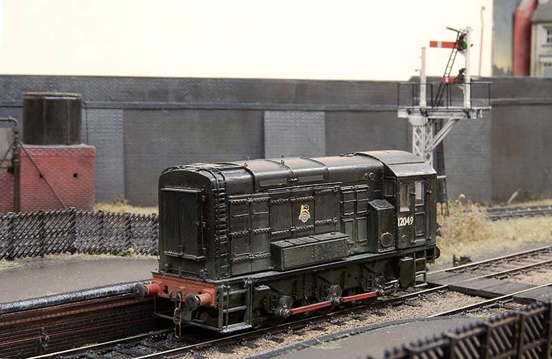
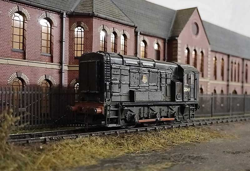
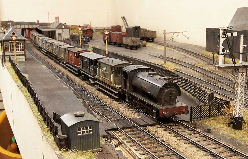
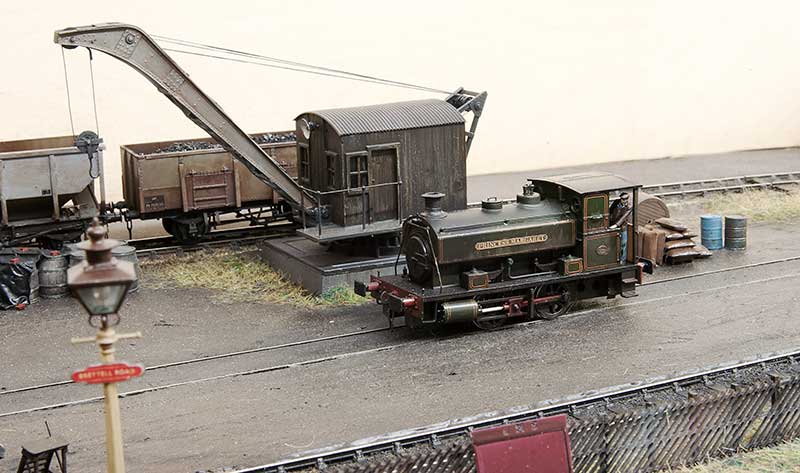
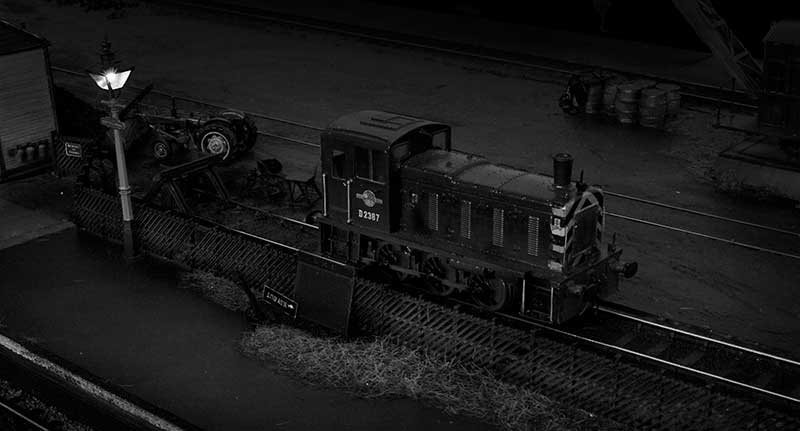
Having had a little trundle to Stourbridge shed and back for some Diesel, Class 11 shunter 12049 waits for the nod back into the yard at Brettell Road.
Years end – more fiddly bits
As 2021 draws to an end I’ve been doing some of those fiddly little jobs that I kind of hope always get lost into the scene but I know they are there. 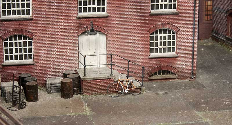 Starting with a pushbike from the Southwark Bridge Models Kit. The kit is for a late 19th century bike so I modernised it a little. I think these may be reduced from 7mm scale model as some of the parts are at the very limit of what will etch and gives you a decent idea of what it must be like to try and solder a spiders web together!
 I’ve finished off the signal wires using MSE posts and easyline.
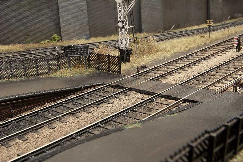 This meant I could finally get the barrow crossing finished too.
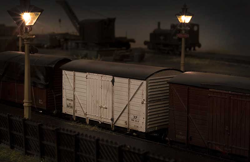
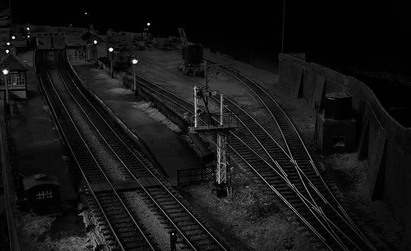
 Below are a few evening shots of various comings and goings.
Hattons Barclay Tank Part 2
One change since the last post on this little tank is I’ve replaced the tantalum capacitors with a Lais stay alive unit on the recommendation of Nigel Cliffe. With this little motor I’ve now got about 4-5 seconds of off the juice running which is a big improvement.
 The model has been finished and lined with Fox transfers lining. I just need the number plate and name which is on order with Narrow Planet. I decided to take a quick shot of it for prosperity before i covered it all in goo!
 And post goo!
 The crew are, the almost customary now, Modelu Figures
 I used to think my Deeley was tiny!
Hattons Barclay tank – part 1
 I never really intended to go for the little Hatton’s Barclay tank despite the Earl of Dudley’s railway having quite a few of them. But one popped up for a reasonable sum on ebay with a best offer option. As it would be a nice to have I put in a cheeky offer and the seller accepted it!
Hattons have done several versions of this diminutive little tank but the main differences are the cylinder sizes. To make a somewhat complicated story very basic theres a 14 inch and a 16 inch version. My model is the 14 inch but the EoD had both types. The other main differences to the cylinders are the wheel size and wheelbase, the 14in version having 3’4″ wheels set at 5’6″ centres and the 16in version having 3’8.5″ wheels at 6′ centres. The tank on the 16′ version was also taller. I don’t know if Hattons have accounted for the wheel sizes and wheelbase in their models but the smaller loco checks out with the known dimensions. One little feature I liked was the pick up arrangement. The bottom keeper plate has traditional wipers bearing on the backs of the wheels but the chassis has sprung plungers that bear on the keeper plate. This means the keeper plate can be removed completely with out any wires to faff about with. A neat little bit of thinking.
Converting to p4
First up, no one does the right wheels. So fancying a bit of a challenge I brought a cheap as chips lathe from Amazon and had a go at turning the RTR wheels down. I had in my wheel stash some old Sharman wheels of the right diameter and salvaged the tyres. I haven’t done anything with a lathe since I was in school and I have to admit I did quite enjoy doing this. Ive always found those ‘someone makes something from rubbish’ DIY engineering videos that pop up in youtube strangely therapeutic. Im just worried now that I want a much better lathe and I’m going to get sucked into turning things next! The axles are a little odd being 2mm but stepped down at the ends for the wheels. A couple of 2mm axles were turned down to match and the wheel sets reassembled with suitable washers. I didn’t secure the drive gear in place at this point.
The clearance between the top of the tyre and the metal chassis was very tight so some time was spent shunting the loco around (without rods and powered by a class 20) to see if it would short and cause any problems. No problems showed themselves.
Despite the rods being too thin (as seems to be the way with RTR steam locos) things wouldn’t fit now the wheels were p4. Handily the cylinders are a separate moulding so they were removed, cut in half and refitted with a 20 thou plasticard spacer either side. The front coupling rod was mounted with the crank pin backwards so that the screw is on the outside of the wheel. This enables the screw head to be flush with the face of the coupling rod. The rear of the coupling rod and the connecting rod were opened up so that a Gibson crank pin nut could be use the wrong way round in fit inside the rods. Both rods were secured with their own nut and the reason for his is thats how they looked on my prototype pictures. More shunting test were carried out and once happy the finals drive gear was secured and the model tested on its own.
DCC
The model accepts a 6 pin decoder and you could simply bung one in and off you go. However with a 0-4-0 a little extra help is never going to hurt. My usual small model arrangement of a Zimo mx633 decoder and a TCS KA1 was not going to fit. I’d seen mention of swapping the motor for something smaller so a little 12volt motor was ordered from Nigel lawton along with an adapter for the worm. For some degree of stay alive 4 Zimo Tantalum capacitors were wired in parallel and everything shoe horned back into the tiny body. It doesn’t give the ‘pick it up and it keeps going for 10 seconds+’ effect that a TCS Kam 4 does but it seems to make a noticeable enough difference to make it worth doing. 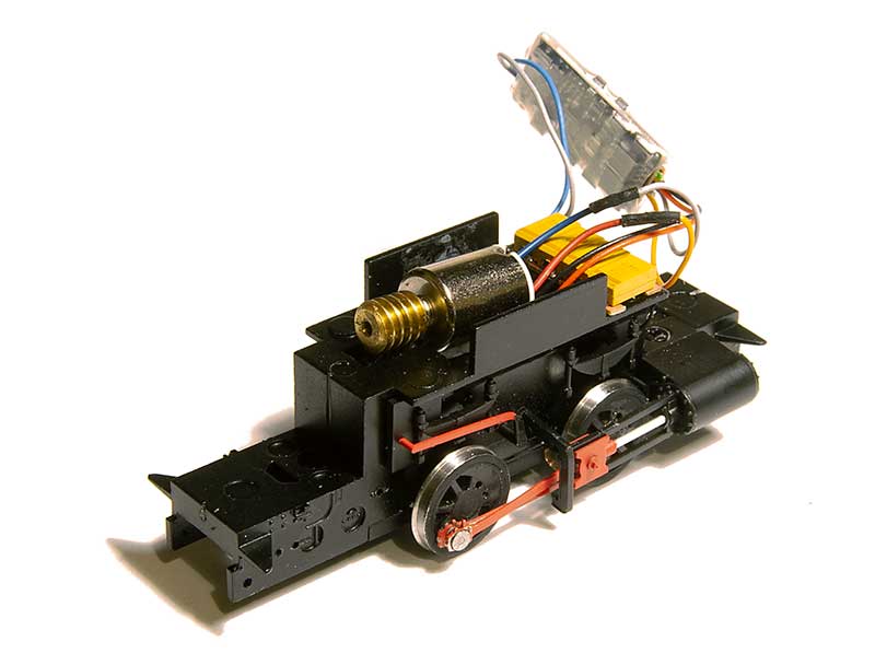
Detailing the chassis.
 As can be seen in the previous picture there’s quite a noticeable gap between the chassis and the wheels. Of the limited detail on the chassis a lot of it pugs in as separate bits so its a relatively easy job to make some new overlays from 60thou plasticard and plug the bits back in.
 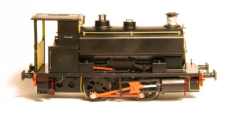 One thing I would advise though is to cut away the original chassis at the points shown (where the NEM coupling pocket is) as you will end up with very chunky and visible frames at the ends of the loco. Might be better to do 20 thou overlays and space them out so they are nice and thin. The arrangement of the brake shoes on the EoD locos seems the opposite way round to the way Hattons had modelled them with the shoes in front of the wheels not behind them and the linkages not visible at all. so these were rearranged. You can see the front crank pin screw in this picture. I also changed the front step to match prototype photos.
The Body
The boiler handrails are separate as supplied but they are plastic, a little wibbly and in a vulnerable place so I swapped them for brass. The weird shaped front handrail was copied from photos. Buffers are Roco HO ones reduced in size. The EoD locos seemed to be set up for lower clearance than the version Hattons supplied so the chimney was reduced in height as were the safety valves while the whistle was relocated from the cab roof to the cab front. The original cab front windows were filled then re-drilled lower down. Some of the EoD locos had a big coupling on the front under the bufferbeam. I suspect this was some sort of auto coupling for when they were working inside the Round Oak steel works. It seems that when some of them lost this they retained the mounting plates which conveniently meant I didn’t have to cut the chassis away as mentioned earlier.
 The rear of the cab. EoD locos had 2 types of cab, an enclosed one with 3 windows and this open version. The enclosed one is available from Planet industrials as a detailing kit. Given the layout is set in the rain my mini driver and fireman must be cussing me for not going for that one! My first thought was to scratchbuild a new rear cab from brass for strength but I decided to cut away the RTR one first to see if that would work instead, as can be seen it did. The handbrake is the supplied RTR one
Planet Industrials detailing kit.
A dash of autumnal weather.
After much experimentation on Brettell Road part 1 and coming up with a working formula. Adding rain to part 2 was a much simpler process (although still a bugger to photograph mind you!)
 View from the middle looking towards Stourbridge. The method I have settled on is to spray everything that needs to be wet with a fine coat of Tamiya smoke. When dry a coat of AK interactive wet effect is added and thats really it. Simple enough now but it took an awful lot of faffing about to get here!
 View towards Dudley
 This is the view from the old layout to the new one . While its not something I intended to capture when I took the picture it does show the elevation changes quite well.
Below a few evening pictures
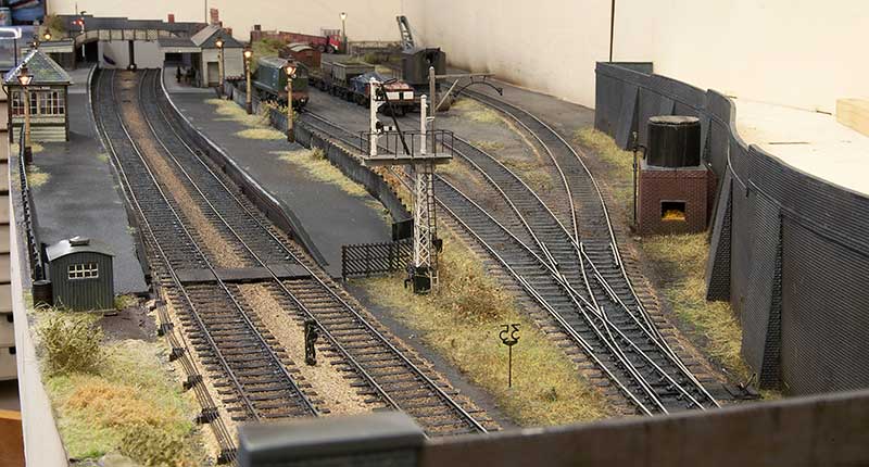
Signals
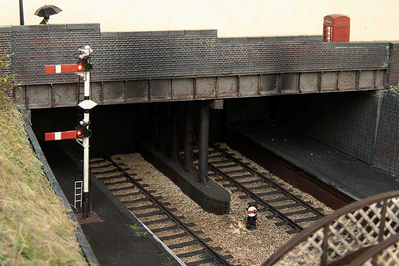
I think I may have mentioned before but one of my favourite things on Moor Street is the mechanical signals. Obviously on New Street there was never going to be an opportunity to do any but on Brettell Road things were different. I had already built a few ground signals on part 1 and an abandoned one but part 2 has given me the opportunity to do some proper, working ones.
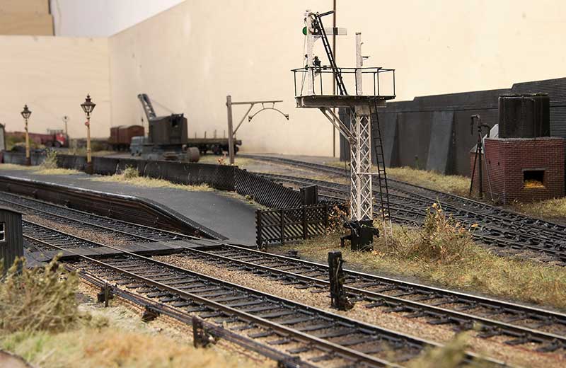
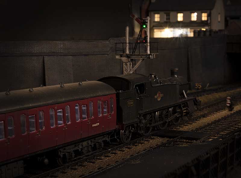
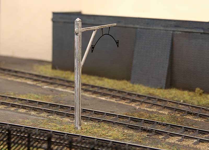
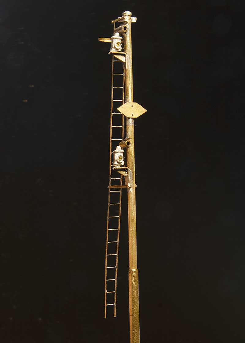 So starting with the post for the simple one. Basically a bog standard upper quadrant affair only complicated by the need to have a co-acting signal due to where the signal stands in relation to the footbridge. The balance weights are below the platforms surface. The parts used are the MSE upper quadrant signal parts (S0012/1), LMS/LNER tubular post caps (SC0019) and LMS Adlake signal lamps (SC0011). The Ladder is from Stenson models and various diameters of tube, sized from the left overs from the signal I built before. This will sit at the Stourbridge end of the platform.
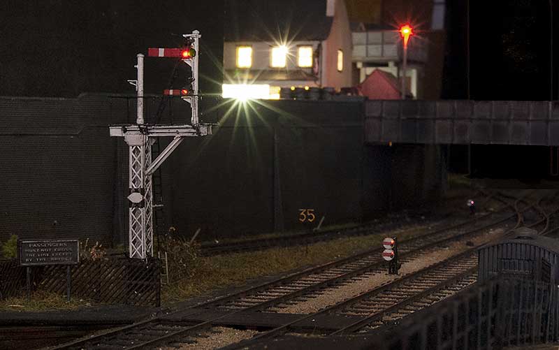
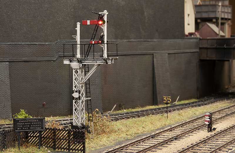
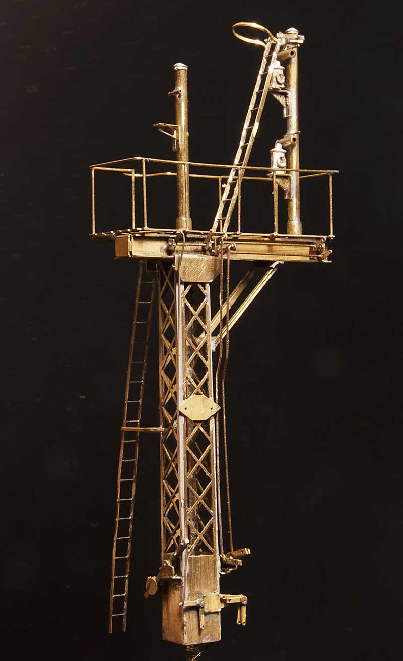 At the Dudley end things are a little more entertaining. So having found a suitable victim (which turned out to be a bit of a mongrel) I set to work emulating what I could see. More MSE bits such as Heavy Lattice Bracket Signal Base Post (S0010) and LMS welded stem bracket (50029) for the platform. The rockers came from the Brassmasters point rodding etch. After I took this photo I decided that the operating ‘wires’ were too big so they have been replaced with no8 guitar strings.
 Platform starter in position.
Gantry in position. The left arm was used for the Kingswinford branch (now disconnected)
Ticking more things off.
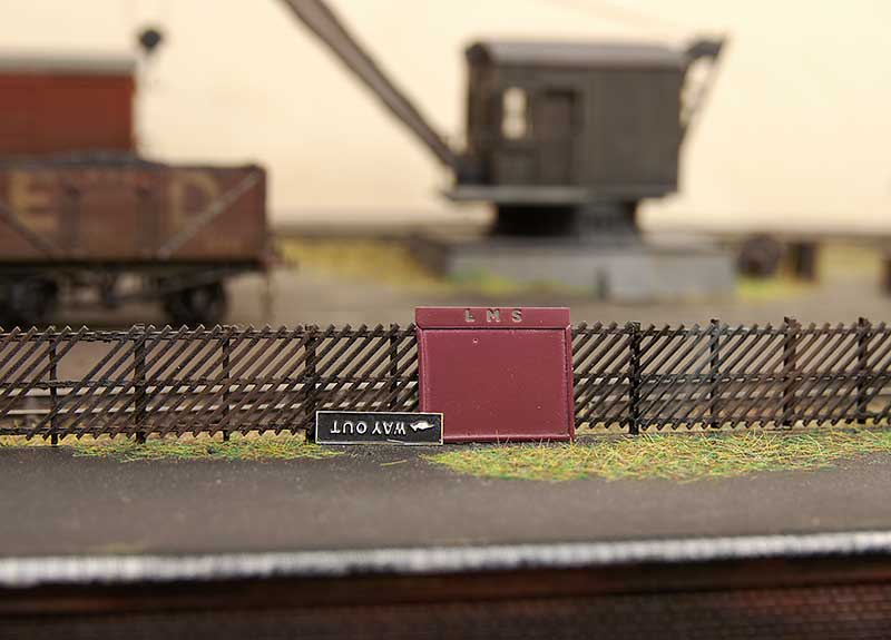
 In order to ‘plant’ my abandoned crossing box I needed a base so opportunity was taken to do a micro diorama and take a piccie first. This is the side no one will ever see so it was worth recording for posterity.
 Here’s were it goes on the layout. One of those little out of the way areas that viewers will need to search out a little. The fence is Knightwing modified to resemble pictures of the real place in the late 50s. Below is the low light version.
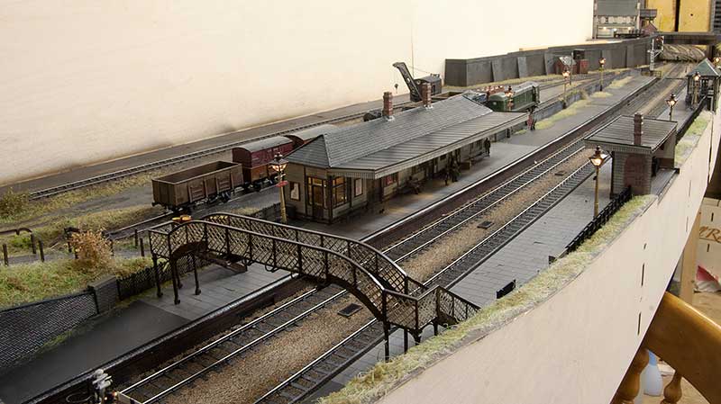
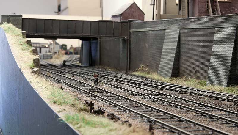
 Ive also finished off my footbridge. In keeping with the rest of the layout (in fact in keeping with everything I do!) it’s modelled to look tired.
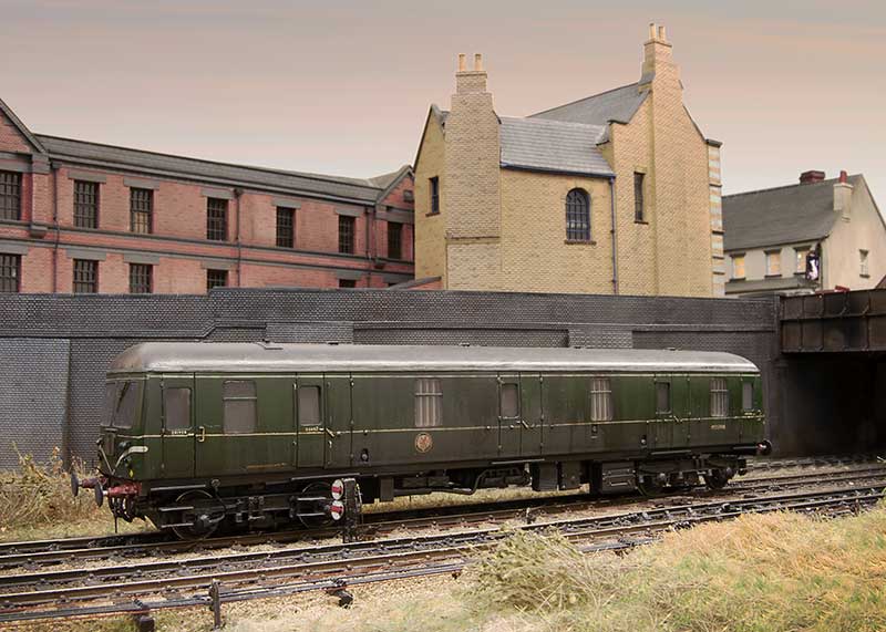
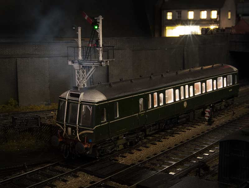
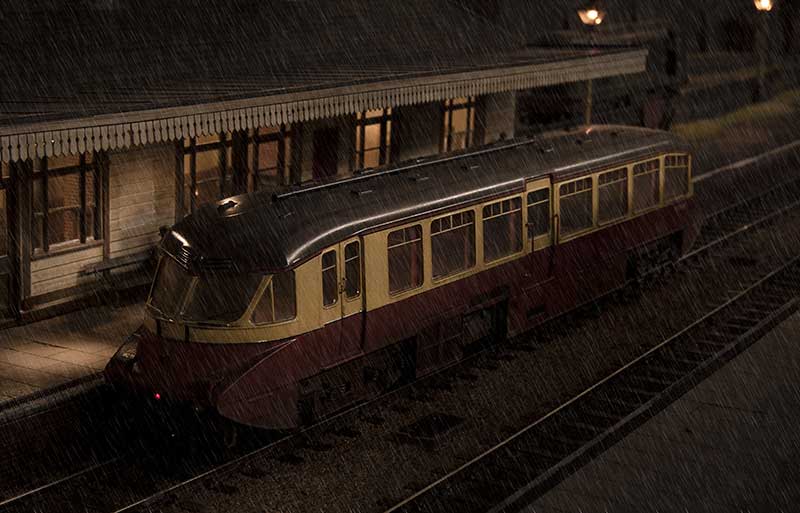
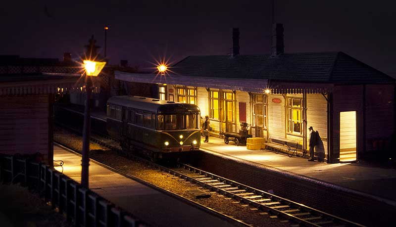 In an effort to keep the line open to passengers a 4 new fangled 4 wheel railbus was tried on the route. The experiment didn’t work out and the station would be closed a few weeks later.
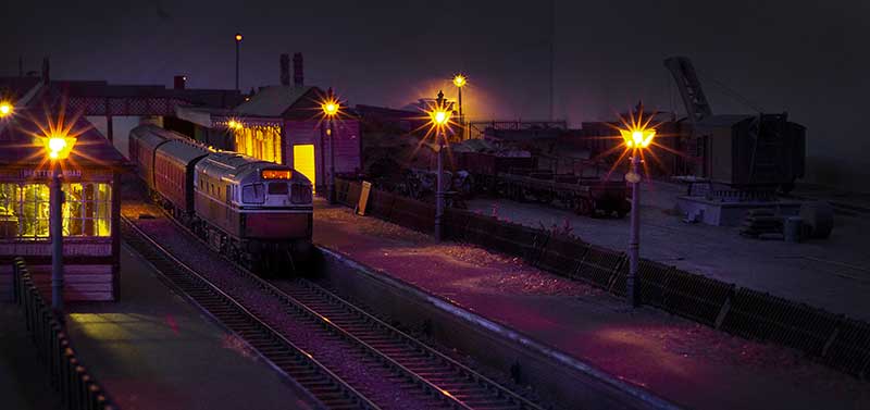 I’ve mentioned before my preference for long platforms and short trains. A BRCW type 2 and its 3 coaches demonstrates the effect I was after.
Little bits of abandonment
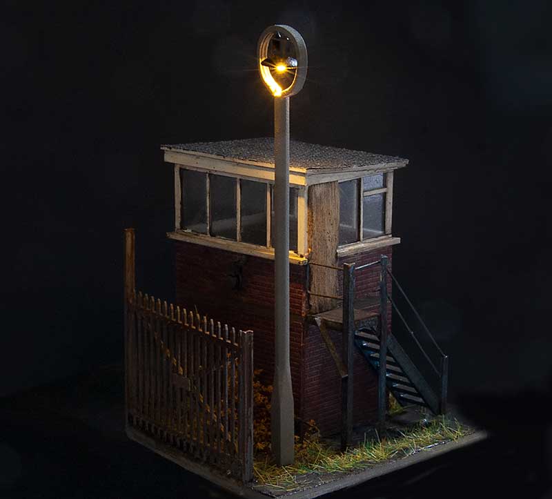
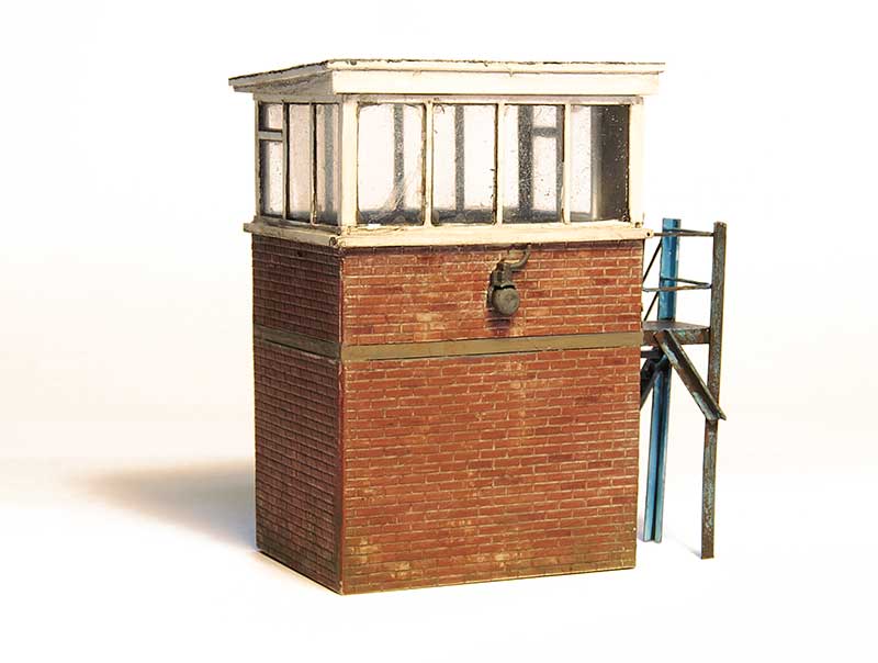 This is a little model of the crossing box from Level Street, modelled in its abandoned state. Ive taken a bit of artistic licence with this as the real building appeared after the layout is set and lasted into the early 1980s. Round oak did tend to move and rebuild things a lot though so a building that became redundant whilst still relatively new wouldn’t have been that unusual for the area. Plus as anyone who’s ever researched a real place will know, not everything at a location will always make a lot of sense. The model is scratch-built with the nifty alarm bell a 3d print kindly supplied by Richard of Mudmagnet Models.
 A few bits dumped agains the platform fence give just a hint that the station doesn’t have long left.
 When I rebuilt my loading gauge (a while ago now) I actually built another one at the same time. The frame is scratch-built from brass sections and the bow from Smiths. This actually serves a purpose as provided the layout is properly levelled this is the point where a free rolling wagon will start to move as the siding descends to the same level as the mainline.
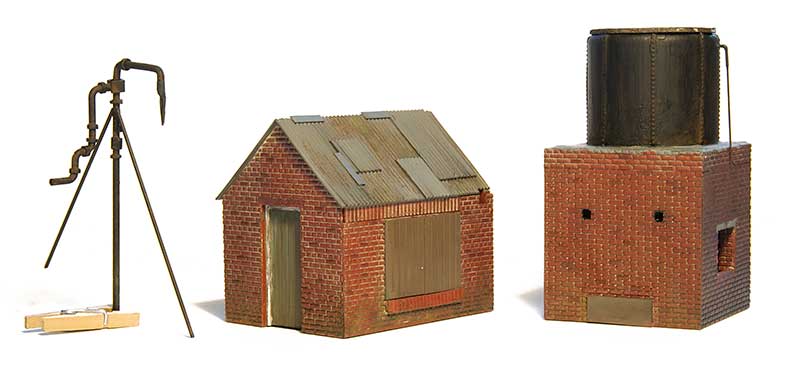 Elements of a rudimentary water tower. The prototype for this stood on the Earl of Dudley’s railway at the link between Oak Lane and Stallings Lane, Near to Himley’s No.8 pit. It survived until 1950. Its Heath Robinson look appealed to me.
 In position on the layout. Its days of servicing the EoD fleet of 0-4-0 saddle tanks are long gone.
A short post in brass
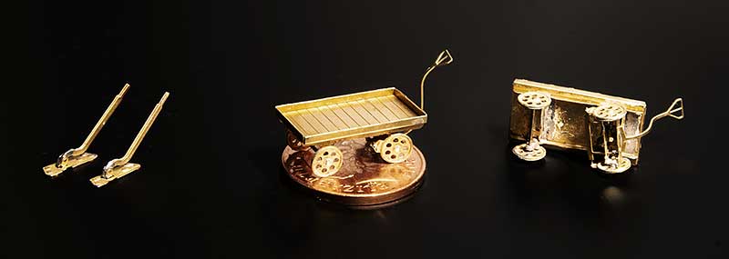 Been fiddling with bits of brass again. I wouldn’t normally bother taking a picture of something as simple as a point lever but I found that the ones I built before were a little vulnerable and easily bent. I haven’t changed the ones i use (Shirescenes) but what I have done is doubled up the levers themselves and they now seem a lot more robust.
I’ve built platform trollies before to but this time I have changed the supplier. I think my previous ones were Scalelink but this one is from London Road Models and is much more detailed. It even had a representation of the brake linkages. Regular readers will no doubt know by now I’m a sucker for this sort of thing! The trolly is shown perched on a two pence piece for scale.
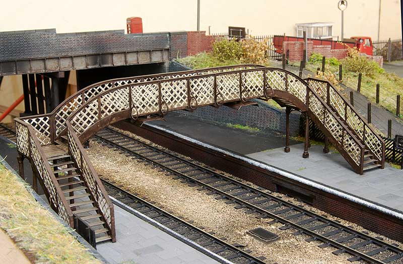
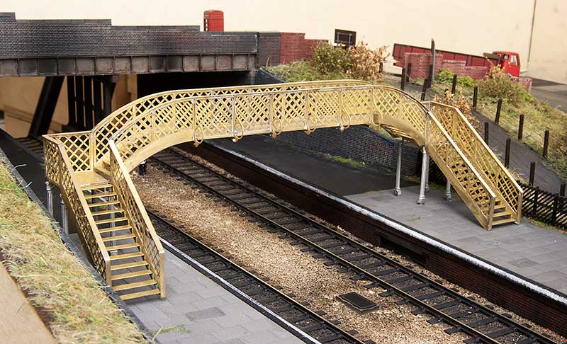 Moving on to something a little more obvious. This is the Churchward models (now sold by Phoenix models) footbridge kit shown in temporary position. As my track spacing is quite wide here I did need to extend the main arch by one panel and, luckily as the etches for the arch are the same, I could use the spare bits that weren’t needed on the facing side. The sides were cut and shut with the new panels grafted in meaning the only bit I needed to fabricate from scratch was the main span floor. An enjoyable kit to build this one.