One working that passed through the real Brettell Lane and kind of fascinated me was the St Blazey to Etruria china clay working. This service ran for years and was somewhat erratic in the paths it took. Usually going via Worcester, Stourbrige then Dudley before heading off to Bescot. Or it could go right at Stourbridge via Old Hill and (I think) Soho Junction. These routes avoided the Lickey but I’ve seen pictures of it going that way too in later years. When I was at University in Stoke it would often turn up at lunch time behind a pair of class 37s although it did switch to a class 60 in the time I was there.
So to have a clay train on Brettell road makes sense as a through service. I like the classic diagram 1/051 clay opens with their sort of cute, baby open wagon look about them. A little bit of rewriting of history is needed though as they tended to stay in Cornwall and not venture out to the Midlands. Brettell Road is set before the introduction of the clayliner service so my justification is that BR was trialing things out to see how they would work and thats good enough for me.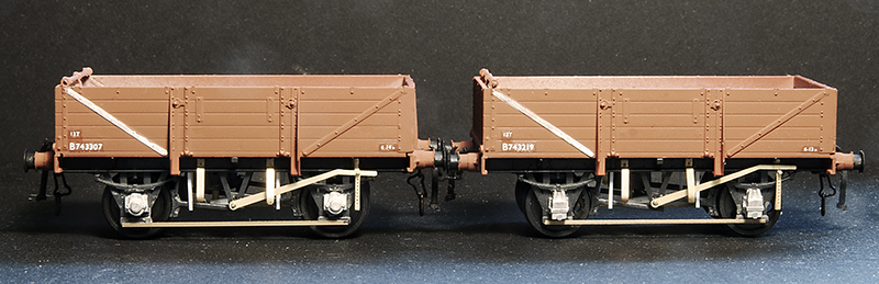
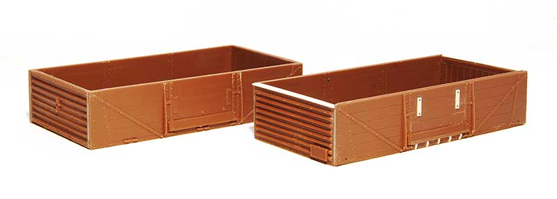
Ratio make a nice little kit for these and I was fortunate to find someone selling a box of 7 on Ebay for what basically worked out as a fiver each. The bodies go together well with a little bit of modification to make the ends fit. The kit features a somewhat crude attempt at a roller bearing and the brake levers are quite poor. It also includes cast buffers that aren’t all that great. So the bearings were replaced with MJT ones although my research showed oil axleboxes to be more common anyway. Brake levers are from the Mainly Trains etch, door bangers from Rumney models and buffers from Lanarkshire models. I did one as a test then built the other 6 as a batch.
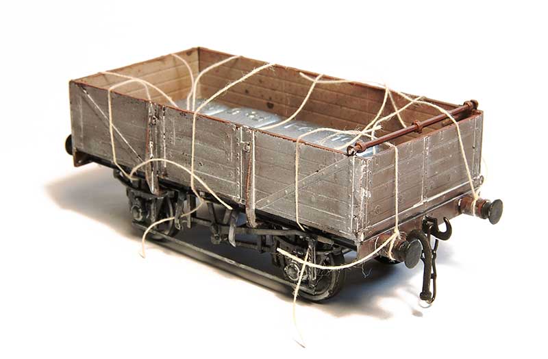
Before I move onto the sheets a bit about the weathering. I followed my usual approach of a wash of dark grime followed by a spray of AK interactive dark mud. This was then all sealed with Klear before AK interactive white ink was used (in various levels of dilution) to give an overall effect of clay staining. You don’t want a fully weathered wagon at this stage, try to think of it as you are aiming for about half the effect you ultimately want.
Previously when I have done wagon sheets I make the sheet up with the ropes attached to it and then attach it to the wagon. This is a bit of a faff and sometimes the glue holding the rope to the sheet can give an odd effect so I approached this a bit differently. Roping of wagon sheets is a whole topic on its own and I will leave that too someone who has properly studied the subject but I just looked at pictures and coped what I saw. So the first stage is to attach the ropes (cotton) to the wagon – Tying it on at the visible ends and gluing to the wagon top with Loctite
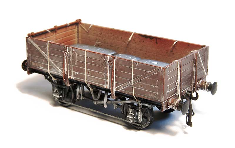 This was then tided up by first sealing the knots with Zap Pink superglue. Theres no huge reason to trim the ropes inside the wagon but it pays to just keep things neat so they don’t get in the way later.
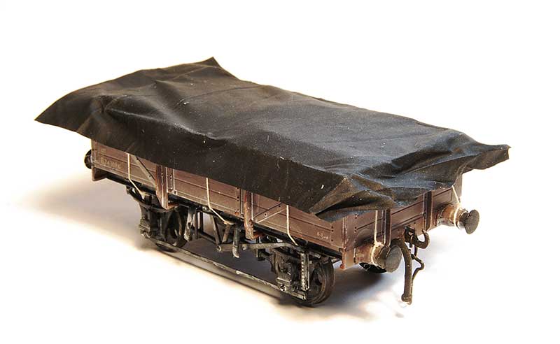
As mentioned before the sheet is made from black latex gloves (actually nitrile) and mine are a brand called Supertouch. They are a bit awkward to cut as the material tends to snag on the scalpel blade even if the blade is brand new. A method I found to work best is to stretch the glove over a bit of cardboard, make a template and to cut it using the handle end of the blade not the pointy end, pushing the scalpel away from you to cut. I don’t know why this makes a difference but it does! As i’ve mentioned in the past the material is black on the outside and a dark grey on the inside. I use the black side as its depicting wet conditions but the grey is good for a nice sunny day layout.
The sheet is then positioned in place, not forgetting to add weight inside the wagon and bulking it up with a bit of tissue first before gluing to the wagon tops in 6 places, about where the ropes are. Use Loctite and start in the middle (it sets very quickly) and remember to pull it taught as you glue the outer sides. This is one of those things were you probably need a bit of variation but you don’t want to force it. I find if I try to be as neat as I can, I’m not all that neat really and I get the variation by default.
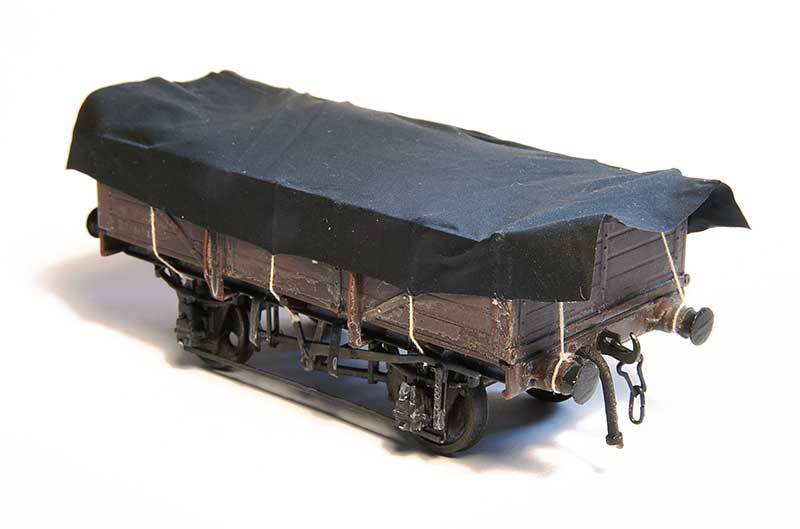
Next stage is to glue the sides of the sheet to the ropes, again with loctite and again puling the sheet taught. I found holding it in place for 10 seconds was all you need. It pays to glue the sheet the side of the wagon at the ends at this stage
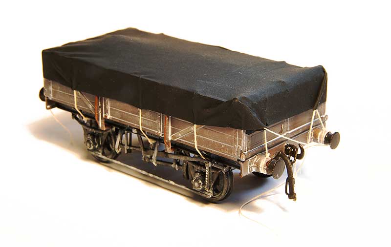
On to the ends. Another drop of super glue on the top and the sheet can be glued in place. The corners can be folded and secured in place and the last set of ropes glued into the sheet itself. 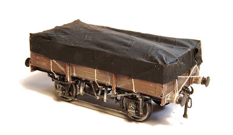
The last ropes tied into place and tidied up.
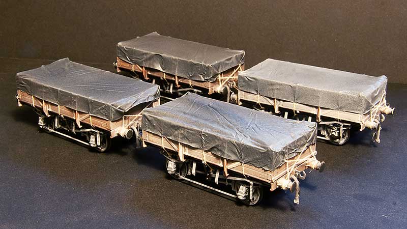
The final weathering, back to the white ink (sprayed this time) with some additional grease stains on the underframe.
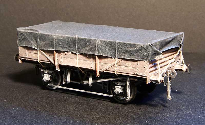 To break up the rake a bit I added a few 10ft wheelbase opens too. These are actually way more typical of the actual wagons used in the clayliners. The ex LMS Diagram 2150 I’ve featured before a few posts ago.
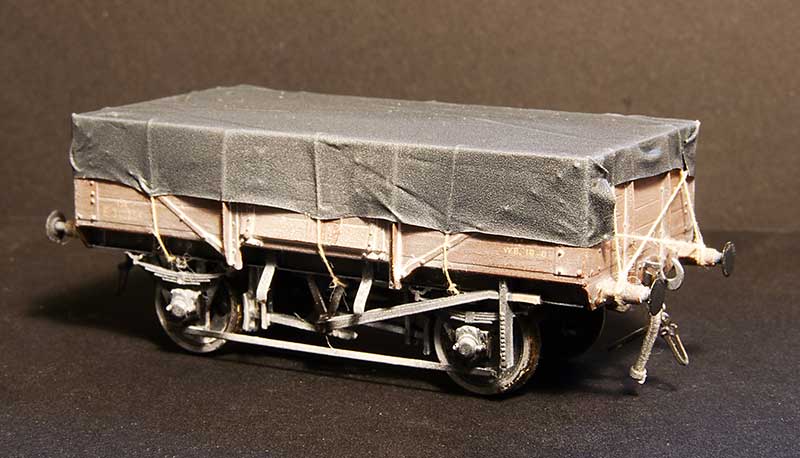
Likewise the ex LNE diagram 210 (although not this specific model)
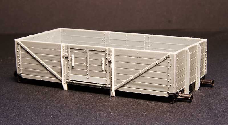
A new wagon type for me is the ex LNE diagram 185. This was constructed from the body of the Cambrian kit C81 for the LNER 12ton 6 plank Open Wagon, With a Parkside 10ft underframe. Theres a few tweaks needed to the body as can be seen and theres an additional top support across the top of the door which is worth adding assuming you aren’t going to cover it over with a sheet that is!
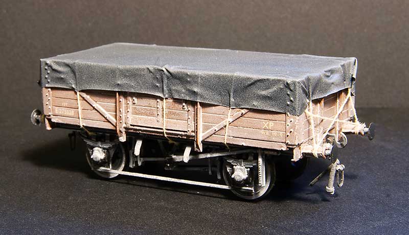
Just need an enterprising transfer manufacturer to produce some sheet markings now.

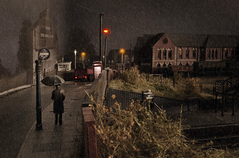 Anyway the subject of this image came up, Apologies for posting it again, I get people are probably sick of seeing it but I have added a bit of rain as some people asked for it. He explained that sodium lighting on a scale of colour gives a very high spike in the yellow range and doesn’t output any other colours. For this image to have the colours it does it would need a white light source, I cant say its the moon because its raining! It actually does have a white light source as I have a string of dim-able LEDs on the wall of the shed that I use to infill my night pictures. He very obviously knew exactly what he was on about! People may have noticed that at night we sometimes see in black and white. It was something I was already aware about on a very basic level. Cameras are much better at picking up colour in low light than the human eye as anyone who recently saw and photographed the northern lights probably noticed.
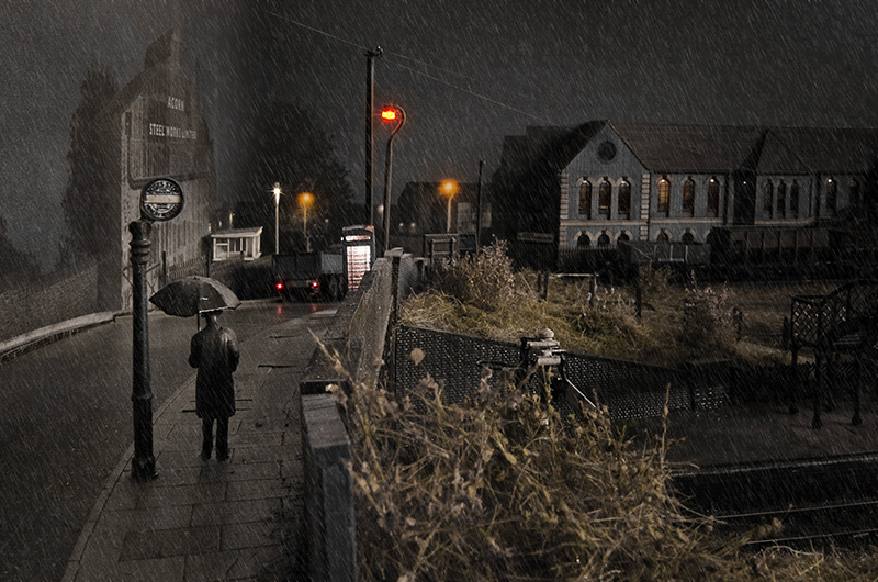 So by taking all of the colour out except yellow (and putting some back in for the lorry lights and inside the phone box) we have an image that more accurately depicts what you would see if you were really standing on a rain sodden bridge in the Black Country at the end of the 1950’s. Two questions now though, The first is which of the two is actually the more pleasing, or nicer image? and the second is anyone actually bothered?
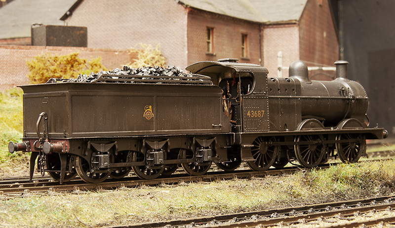
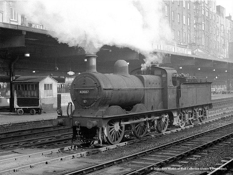 I found this image of 43687 at New Street on station pilot duties around 1957. The loco was allocated to Bournville shed at the time so it seemed suitable to me. Image ©John Turner 53A Models of Hull Collection and used with his kind permission.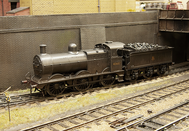
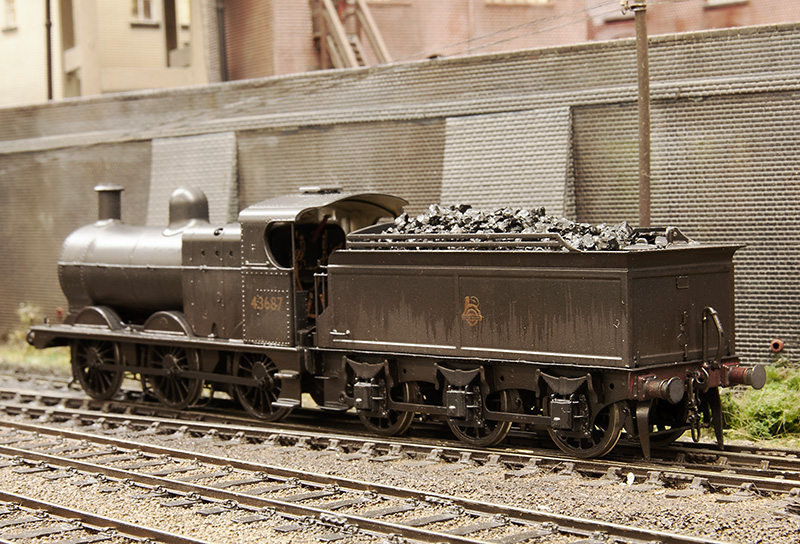
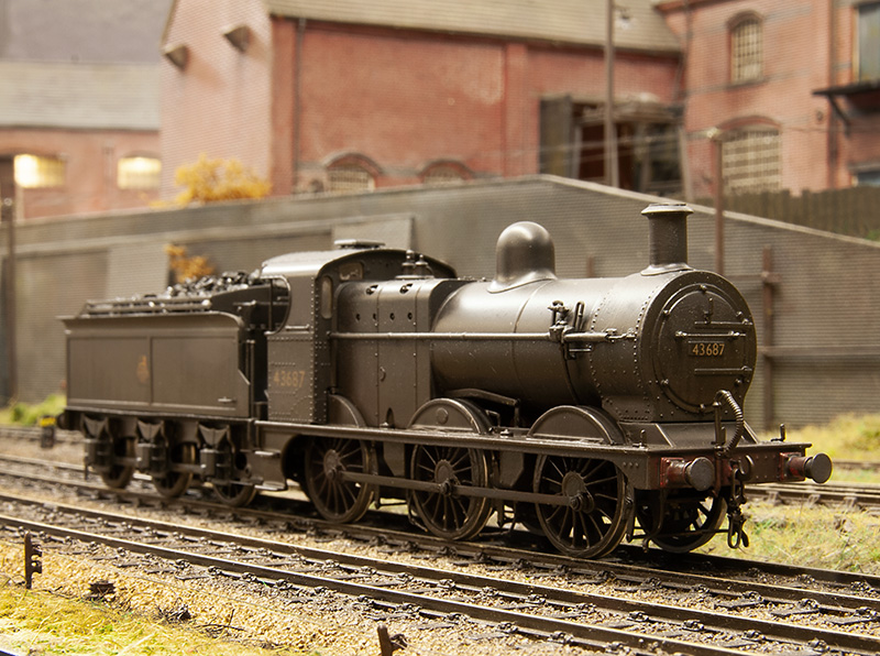
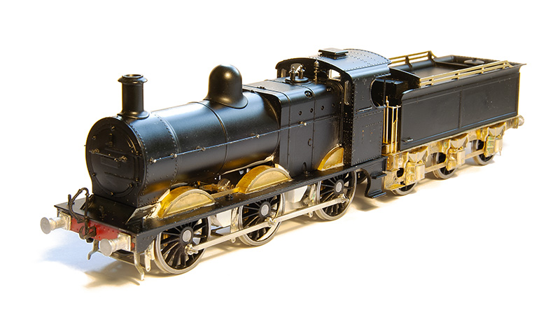
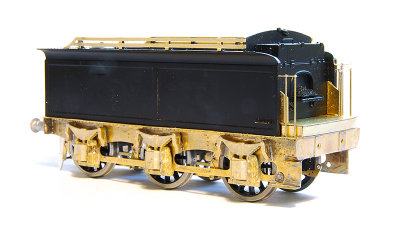 So starting with the tender. I never had the Bachmann chassis and if its anything like most RTR tender chassis it will no doubt have all been a bit flat and kinda naff. Brassmasters do a detailing kit to replace the tender chassis completely so I used that. This is just built as per their instructions.
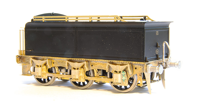 The rear end. Buffers are from Lanarkshire models as is the vac pipe. I think I’ll replace the lamp irons too.
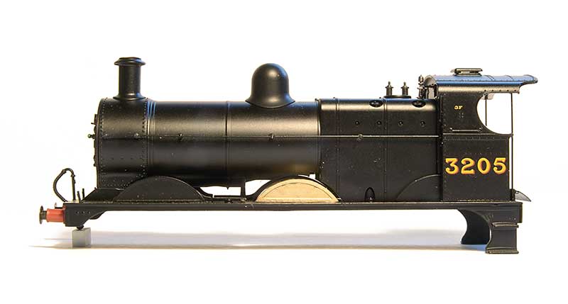 Before I show you the chassis though some decisions need to be made. The splashers suffer from the usual RTR problem of being too big. Brassmasters do a separate etch for ones that are the right size. The above image shows a comparison so you can decide if it bothers you or not.
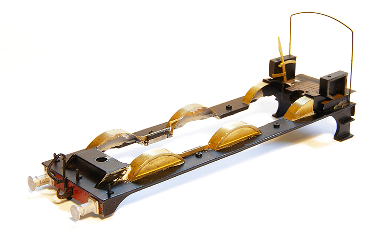 As you can probably guess it bothered me so they were all replaced. The original footplate has a solid floor back to the front of the chassis casting so I cut that out. The new reversing lever is part of the chassis kit and the boxes on the side of the cabs have been thinned down by 2mm as per the instructions.
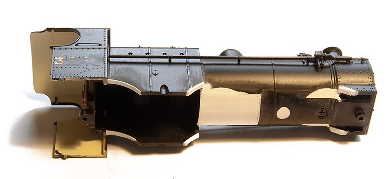 All this means that a little bit of rectification is needed on the body as it had recesses in the boiler for the original splashers that are no longer needed. I believe the Bachmann chassis block comes quite far forward so the base of the boiler was put back in using layers of thin plasticard. Theres not really much else to do to the body other than this.
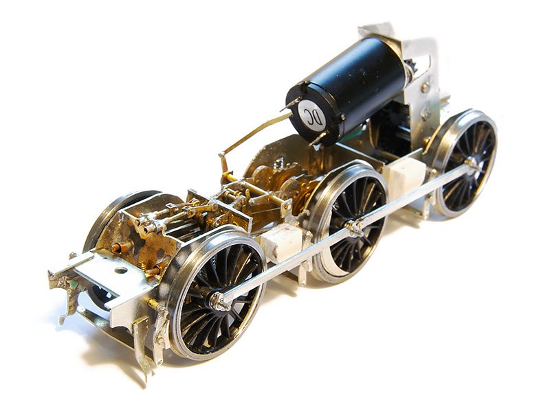 Back to the chassis then – with the inside motion kit from the 4f – You didn’t expect me to leave a gaping hole did you? The gearbox is a high level loadhauler+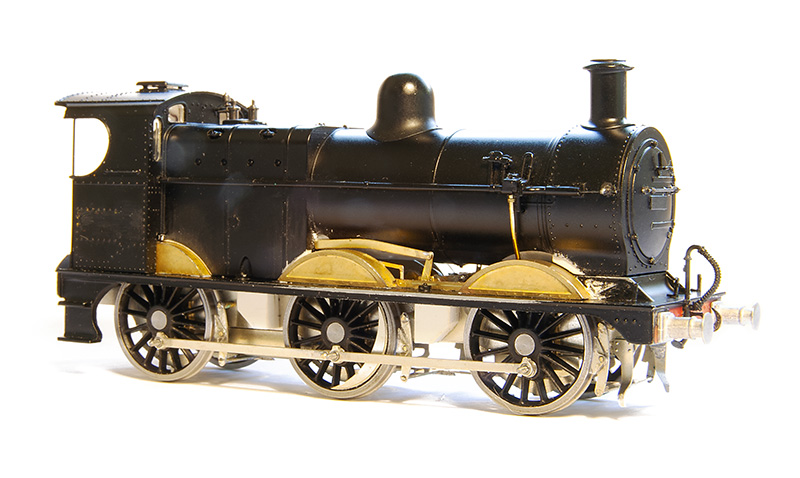
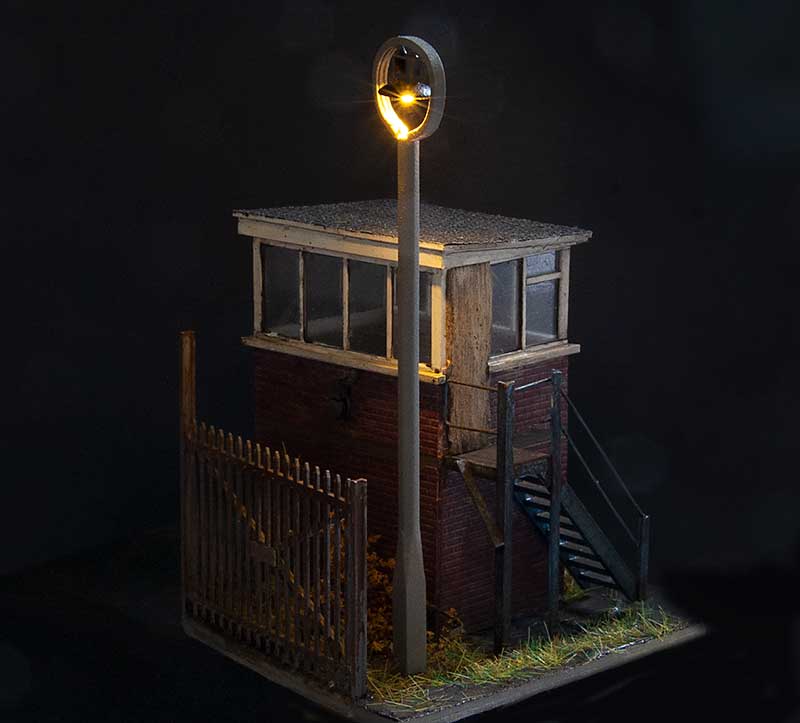 The first was prompted by a failure. It had always irked me a little that the above lamp was a little bit crude and the top wasn’t really the distinctive shape the lights at Round Oak had. Being at the back in a dark corner it wasn’t noticeable enough to invest any time into. However when it recently failed why not kill two birds with one stone?
 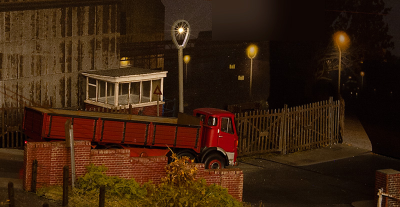 So after a bit of tweaking I’m much happier with it now.
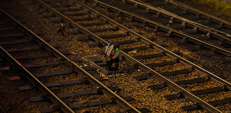
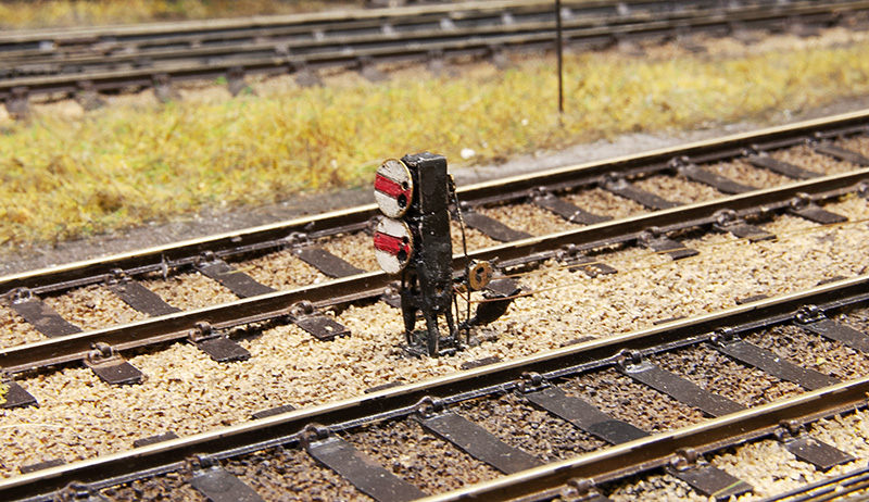 Ground Signals. I originally used the MSE kits but I had found a few drawbacks. First thing was A few had took some knocks while cleaning the track. As they use a whitemetal casting for the main body and legs they really didn’t like this at all and were starting to look a bit bent and battered. Secondly as I had fitted lights there wasn’t a lot of room to work and I had just drilled out the lamp housing and shoved a nano LED in there with slightly mixed results.
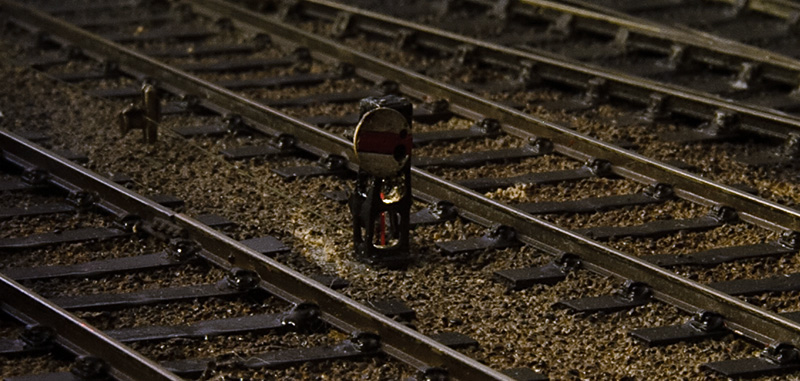 One consequence of this wass more light bled out of the bottom than through the signal despite various attempts to fill the hole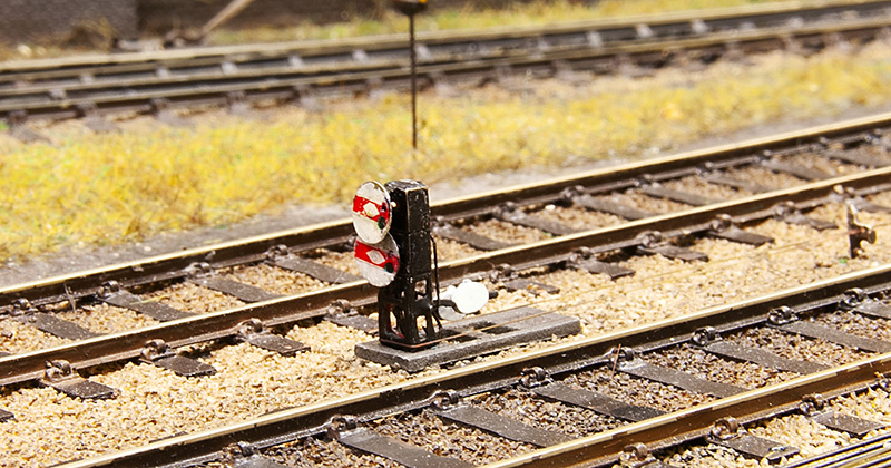
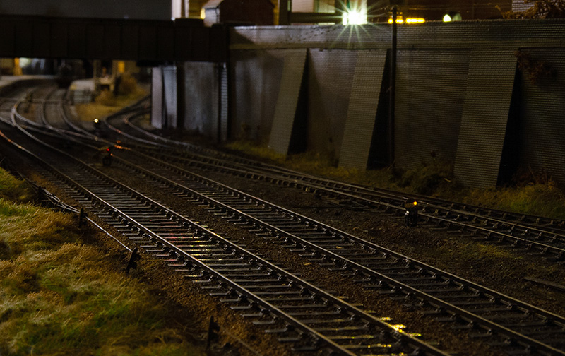
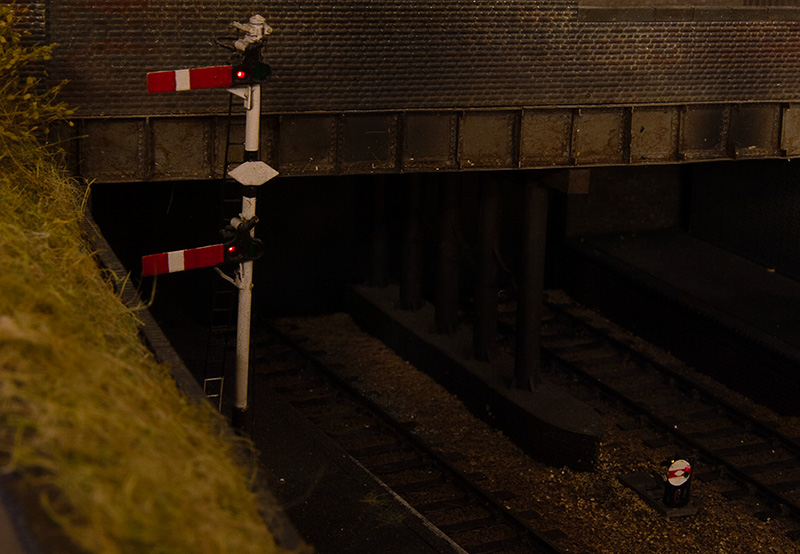
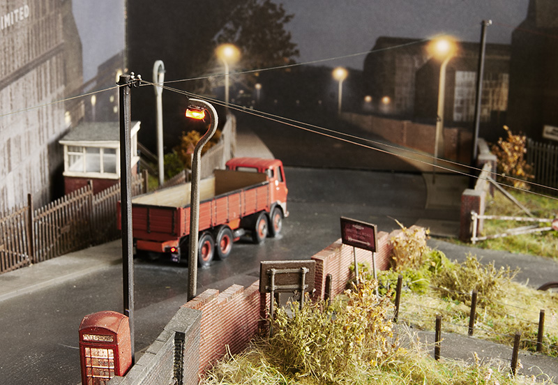
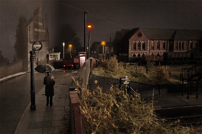 A revisit to my classic (or is that cliché?) scene. This time a wider verson.
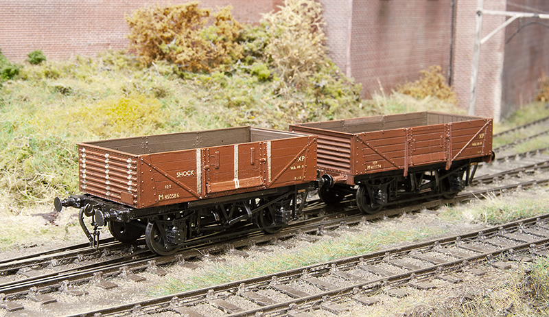 The finished wagon in the company of yet another D2150 13t open.
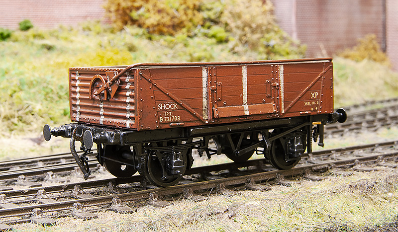 The BR wagon has had a Rumney models sheet rail added and been mated with a clasp brake chassis to produce a D1/040 variant. Buffers are from Lanarkshire Models.
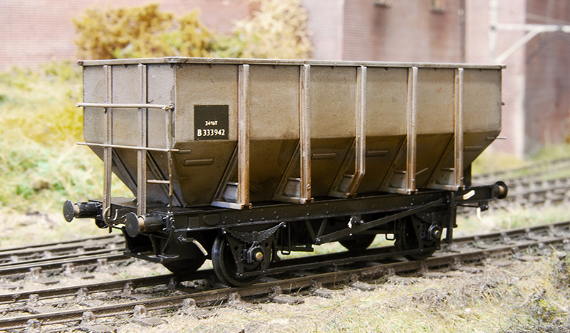 First up the Accurascale 24.5t hopper which i picked up cheaply from a private sale on Western Thunder. It came in brown livery and with a certificate saying it was a limited edition number 061 of 500. If this sort of thing matters to you and you have one you will be pleased to know that your model is now even more limited being 1 of 499 (You’re welcome!). It was separated into its component parts (a process that had already started in the box) and the body resprayed. These are not a straight drop in wheels job as the axles used are a little short and theres a boss on the back of the W-iron, much like Lima was doing 40+ years ago. Its not a huge problem though as a few turns of a bearing cutter (I use Ed’s tool) and a little bit of thinning the boss down and off you go. I also cut off the NM pockets.
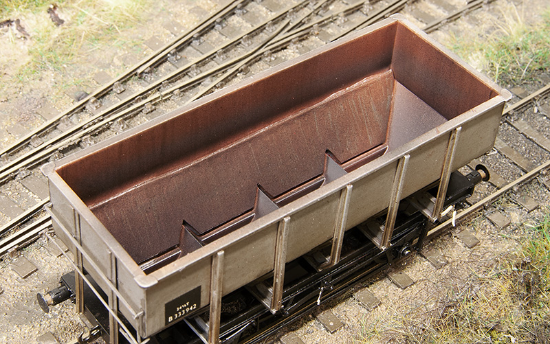 My solution was to make new lower sides from 1mm lead. This brings the wagon up to 50 grammes. If you would like to follow suit I drew up a little cutting template which you can download from
 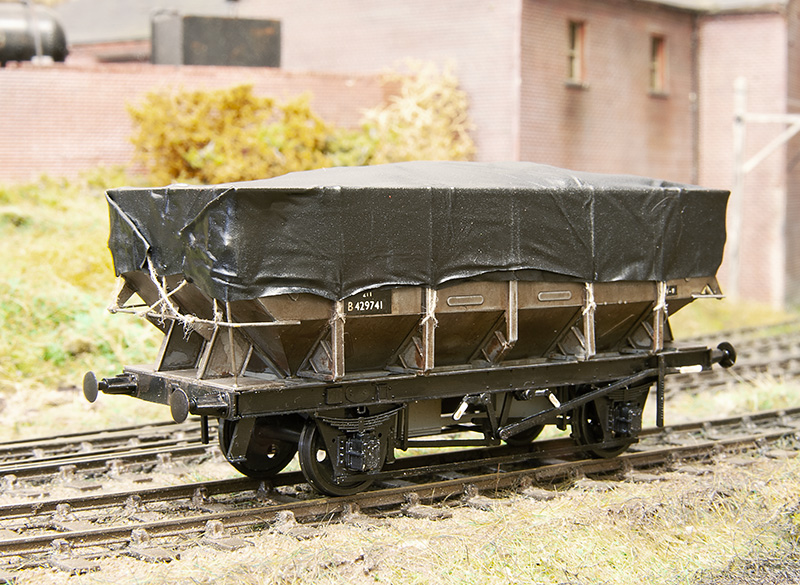 Another parkside 21 tonner based on a picture that came up on my facebook feed. (some of the wagons in the post are waiting a delivery of couplings you may notice). Theres often a discussion when these kits crop up that they are difficult to build but they really aren’t. The trick is to assemble a side and end as 2 pairs on a piece of glass with a cutting matt to ensure they are square, let these set fully before assembling the rest of the wagon and theres no problems Any slight gaps between the panels can be filled from the inside using Mr Surfacer 1000 liquid filler.
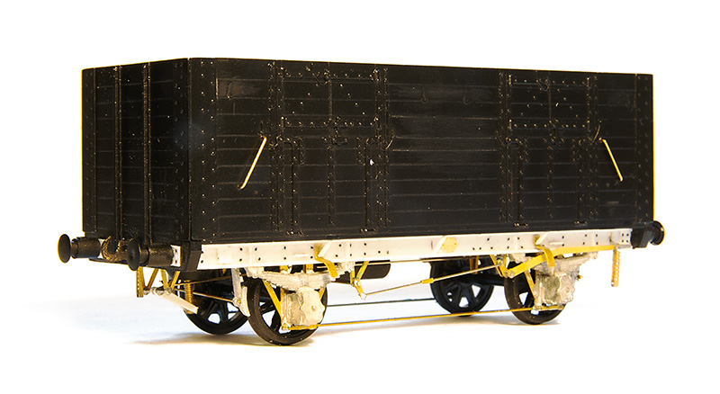 Now a few oddballs – this is an ex L&Y diagram 81 loco coal wagon from the old MAJ models kit. The kit is supplied with a wooden chassis which is correct for the earlier wagons but i wanted the later one so only used the body. The brake gear on these were a little weird to say the least
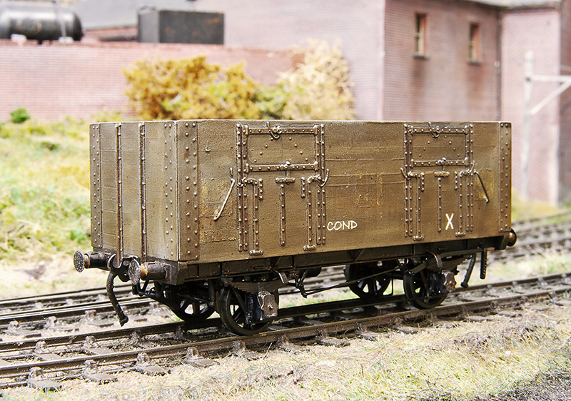 The plan is to have a short train of condemned wagons that is delivered to the yard as a trip working from Bescot. These are then to be collected by one of the Round Oak locos to be taken away for scrapping and the metal bits melted down in the furnaces. This is basically what happened and quite a few locos met their fate this way in real life. Unlike some of the more famous railway scrap yards stuff didn’t hand around for long so nothing from my scrap train will have any hope of reprieve sadly. The condemned markings are from Railtec,
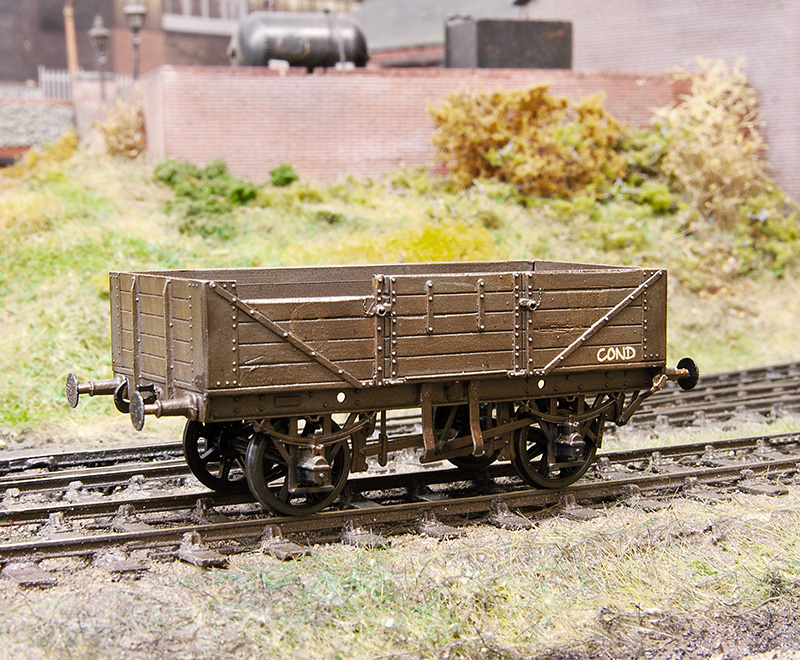 Another victim this time a GWR diagram 04 open from the cooper craft kit. Like another Coopercraft kit I’ve built this has the bearing holes mounted too low meaning that the wagon looked like it was on stilts. This one has slightly odd brake gear as well. You can just make out the old GW branding.
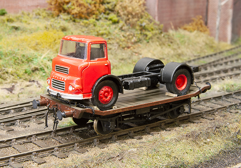 The LMS traction truck has finally been mated with its load.
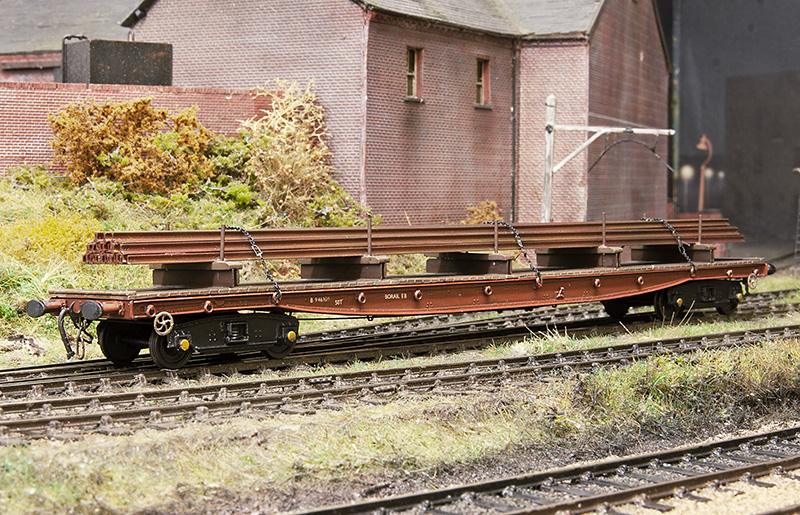 Also based on a picture that cropped upon my facebook feed is this Borail from the Cambrian kit. Making the load was far from the most interesting task I’ve ever done I can tell you and despite it being essentially hollow this wagon still hovered up 5 meters of rail!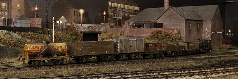
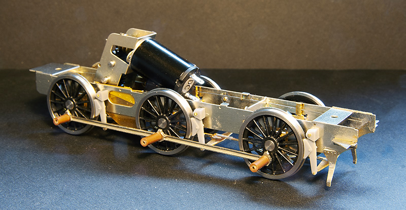
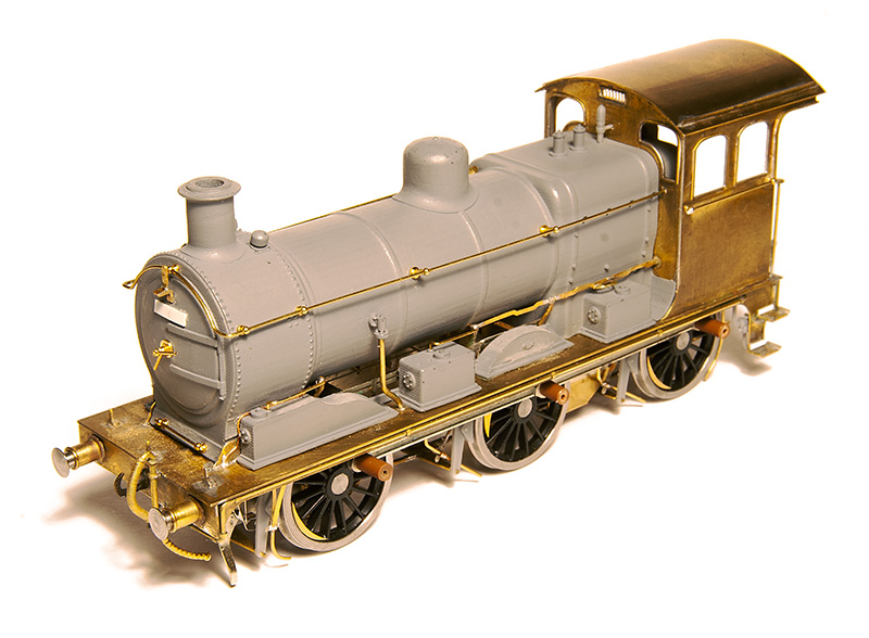
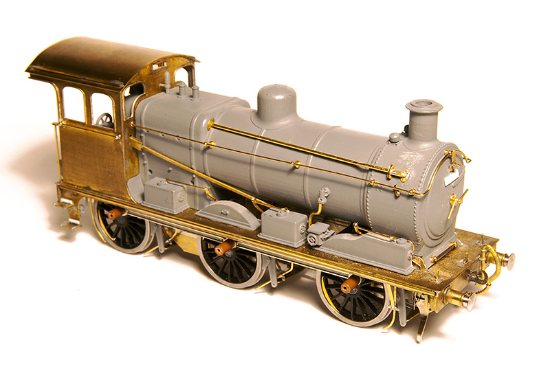
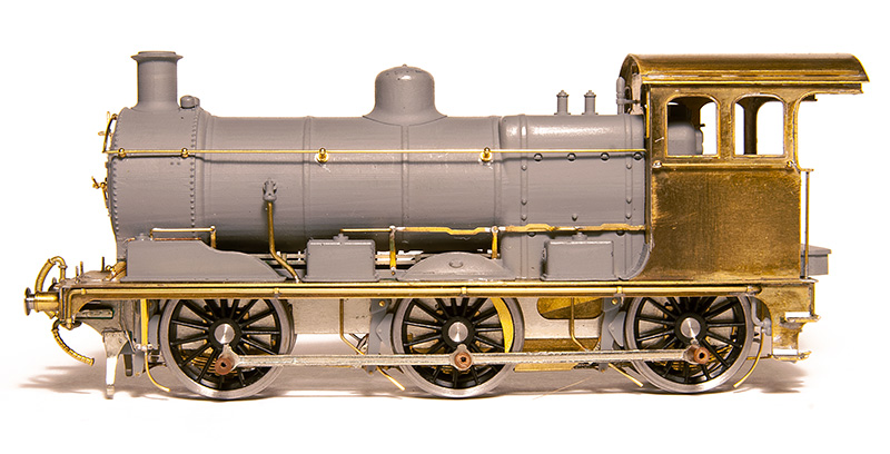
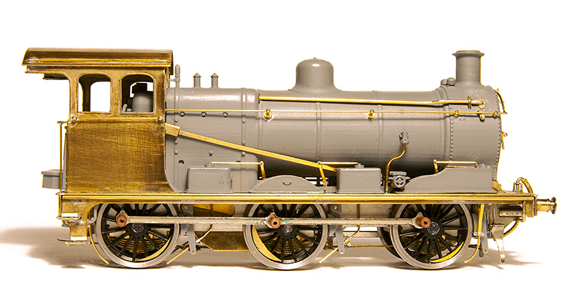
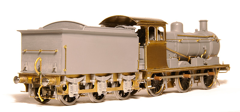
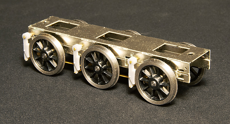 The tender subframe – Again with options on the brake shoes.
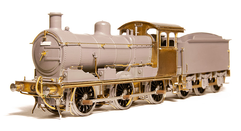
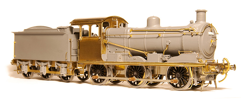
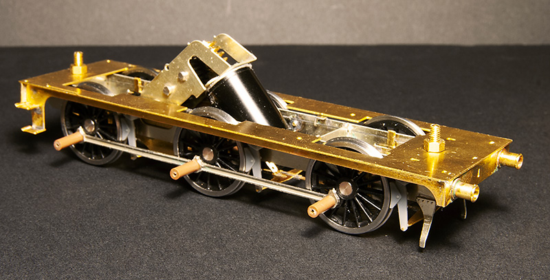 Chassis and footplate.
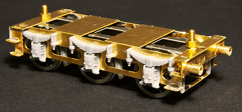 Tender with its outer frame.
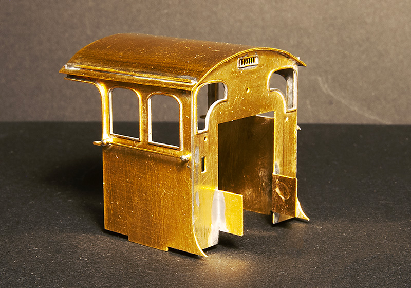 The cab
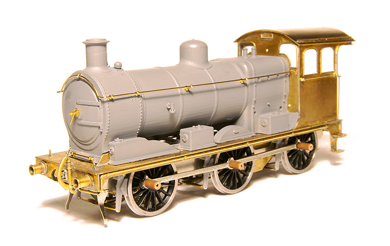 Pretty much everything above the footplate and forward of the cab is catered for by a 3D print. Here I’ve made a start on the basic detailing
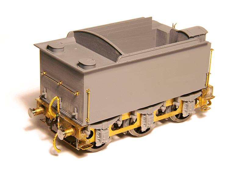 The tender body, like the loco, is a 3D print.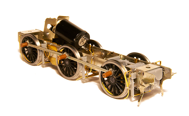
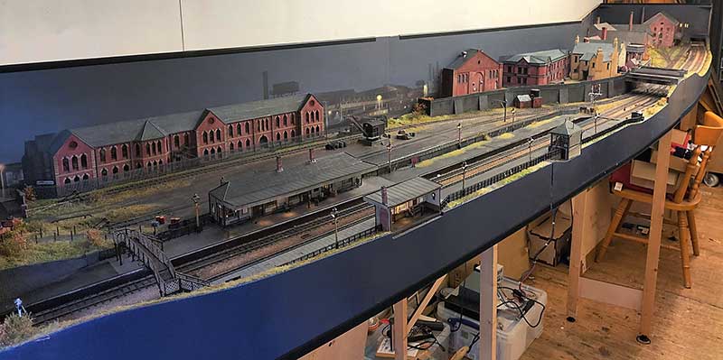
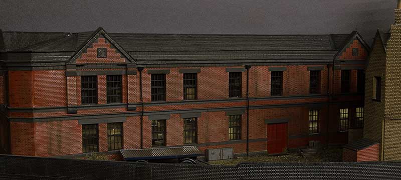 The lights on the upper floor of this building failed before the show but after the building had been planted onto the layout. It was too close to the show to fix it before so this is something to look at now I have time. I also want to add a few yard lights and sort out the telegraph poles on the layout because as they stand now they don’t make a huge amount of sense.
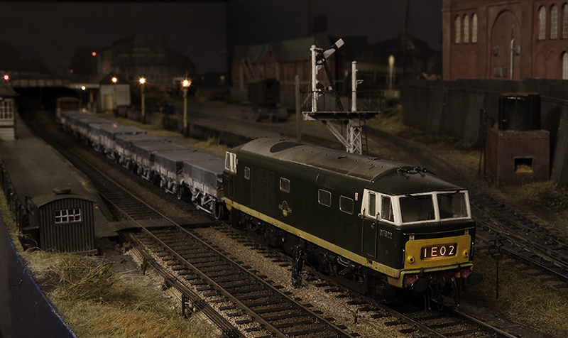
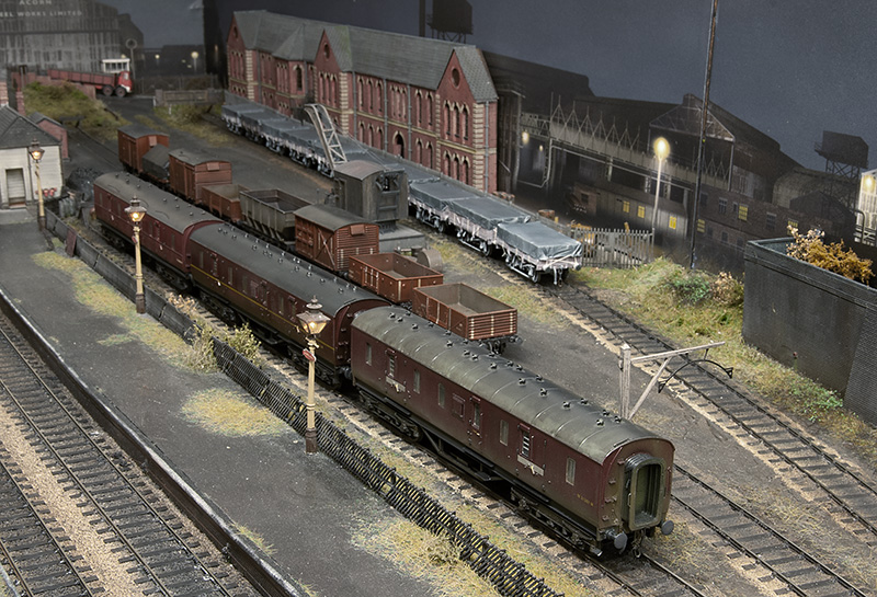 Since the show I have a small stockpile of new rolling stock to be tested. The rule is all stock must go everywhere without falling off, even though in this image only the middle road of wagons will go into the yard at shows. Of this little lot only 4 wagons were rejected and returned to ‘works’ for some fettling. These 4 have now been passed too.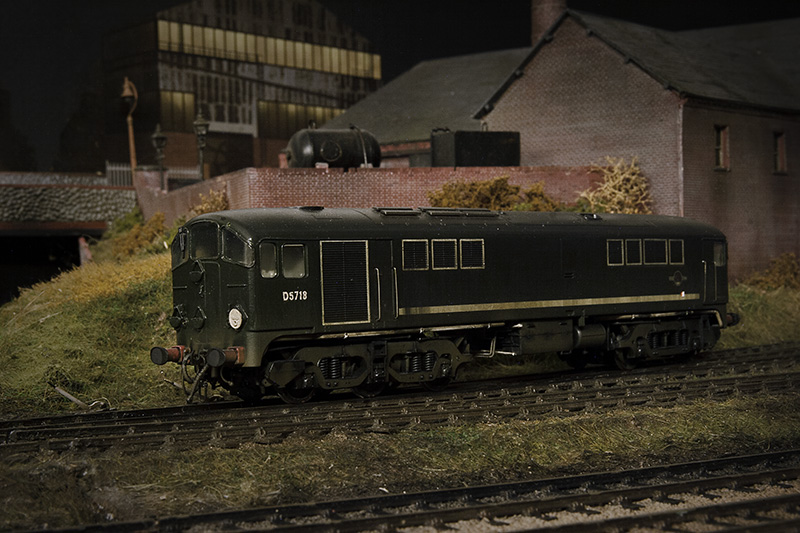
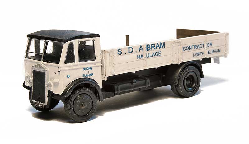
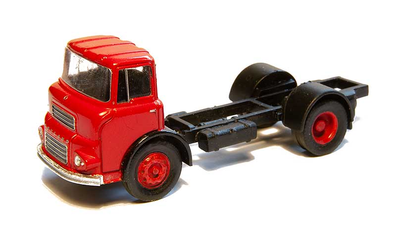 A leyland LAD cab and chassis, destined for a wagon load on Brettel Road. The cab is Base toys with some minor tweaks and windows added to the rear. I was aiming for a new vehicle being delivered and wanted an open chassis. The source for this was a cheap Langley Models kit for a Guy Otter/ The chassis was shortened and wheels are from RTI.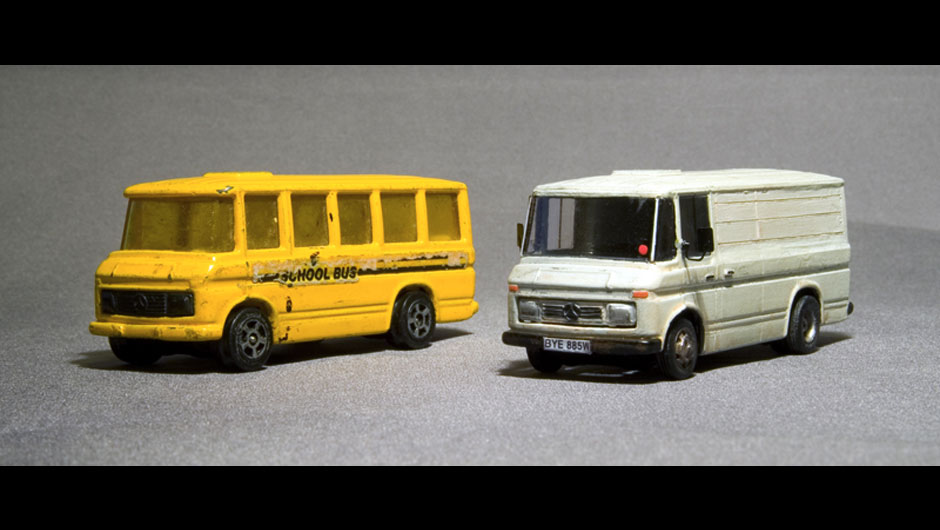
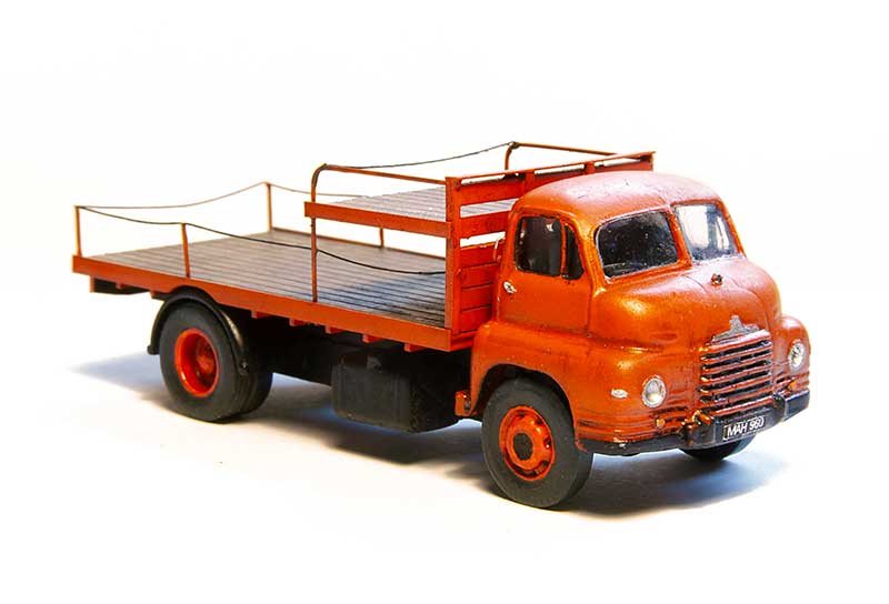
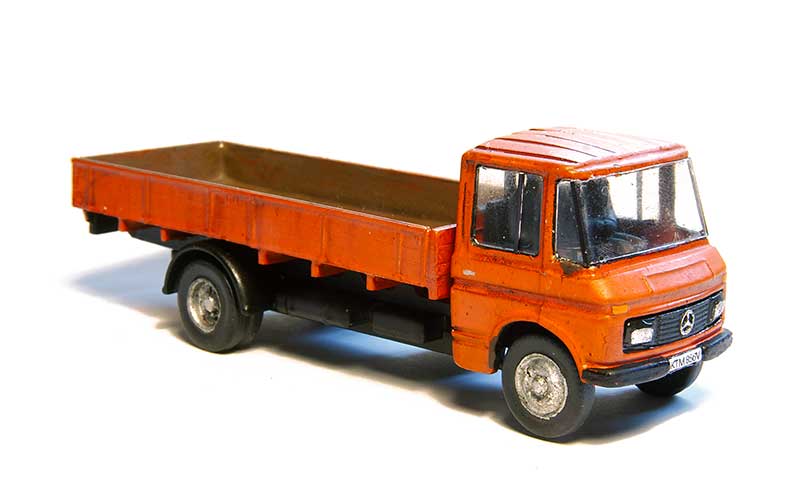 The Body is from the previously mentioned Langley kit mated to a Base Toys chassis and more RTI wheels. I need a spot of work with a sheet of sandpaper on a flat surface to get it to sit properly. This will be a reasonably old vehicle on New Street.