A trio of tanks.
A trio of tanks this time starting with…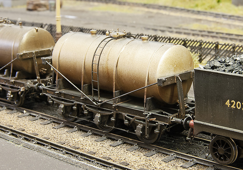 … the LMS milk tank I featured last time. Now ready for service.
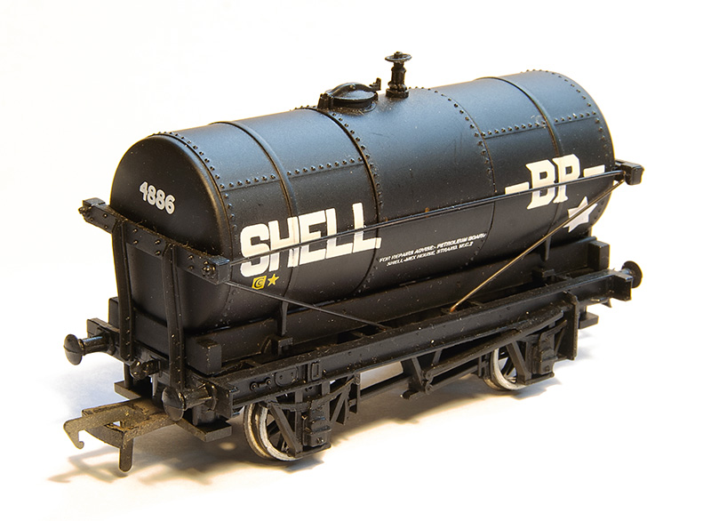
The Bachmann 14t cradle mounted tank wagon. Very much of its time with a very generic (and pretty rubbish if I’m honest) chassis. 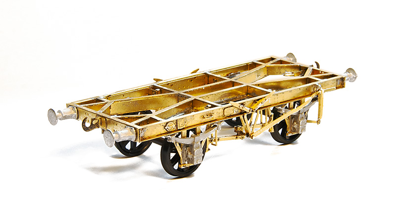
Luckily Justin does something a little more refined and very nice to build it is too.
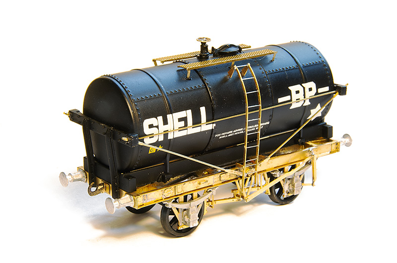
Ready for the brass bits to be painted. The ladder is only loosely in place. The walkway is from my box of useful stuff (I think Stenson models) and the buffers are from Lanarkshire Models.
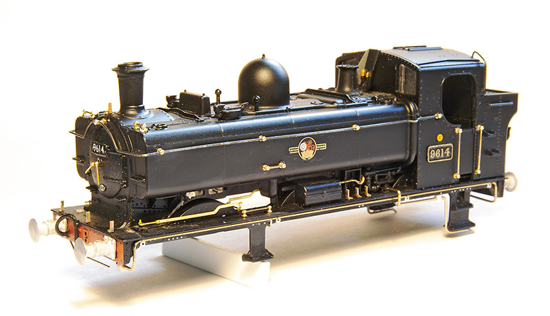
Still sticking with the theme of tanks but is a slightly dubious way, work in progress on a 96xx tank. I originally picked this up quite cheaply with and idea to include it in my scrap train. Round Oak scrapped quite a few locos, but it didn’t take me long to decide to do it as a working loco instead. Especially as a picture of this very loco heading a freight train through Brettell Lane cropped up in my facebook feed.
As far as I can tell this model by Bachmann is an evolution of the Mainline model I’ve already used to do my 57xx tank, with a later cab and other refinements. All of the handrails are separately fitted but I felt the handrail knobs were way too big so I replaced them with Alan Gibson ones. I reused the long handrail but as its not so wide i had to cut it in half to lose a little from the middle. The sandbox fillers are too far forward as they were repositioned with RT Models linkages but not before the front splasher was cut down in height. A compromise for the over sized flanges on the RTR wheels and something that has entered my ‘now I’ve seen it, i cant unsee it’ mindset when looking at model steam locos. Smoke box dart is also Gibson and the lamp irons are from Masokits. I also replaced the pipes on the footplate. Some 96xx had a bracket half way along with i quite liked but unfortunately 9614 was one that didn’t.
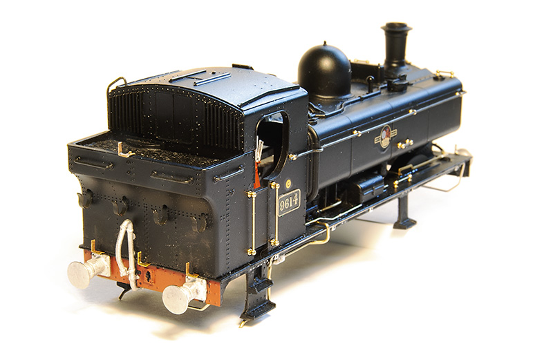 Rear view. The lamp irons were too high up on the bunker. This is correct for a 57xx but on the 96xx tanks they were lower. I was replacing them anyway. Buffers are Lanarkshire models. I prefer a better detailed solid buffer over a less detailed sprung one.
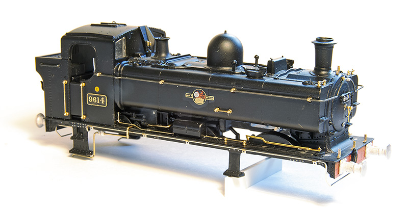
Drivers side. The pipework just in front of the cab is the same on both sides of the model. Again OK for a 57xx but on the 96xx they were different with a somewhat more barren look on this side. The footplate pipework is also routed differently around the cab footsteps. Chassis will be a high level one with my working inside motion bodge as described here. https://p4newstreet.com/an-unremarkable-little-tank-engine-part-1/
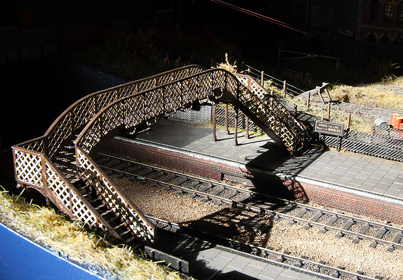 Finally something that you will never see – Brettell road in the sun! It was coming in the shed door and caught my attention.
Flights of Fancy – Part 2
 I ended the first part of this project by mentioning I needed some bits from Scaleforum. One of these was the injector which I modified a little from an Alan Gibson one.
 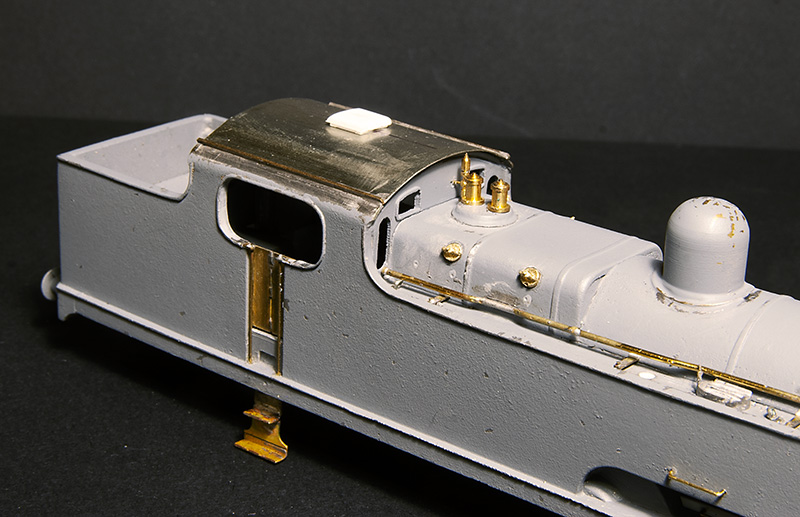 I also needed some firebox wash out plugs. Again Alan Gibson did the honours. It’s worth noting that they are not on the same places either side. The cab roof was just a bit of nickel silver rolled to the right radius and a few bits of strip for the rainstrips. The vent was filed up from Evergreen section. While on the subject of the cab the kit includes some bits and an etched floor. I found the handbrake column, if mounted to the cab floor as the kit was designed, gets in the way when trying to mate the body and chassis together so I cut it from the floor and mounted it to the body instead. The kit specifies that the reversing screw is mounted on the left side of the cab but, while hard to see in photos, it seems to be mounted to the right side so thats what I did.
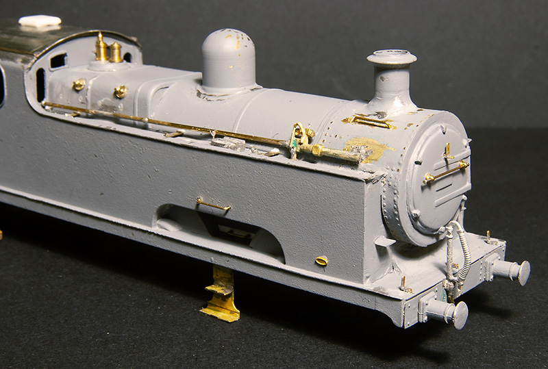
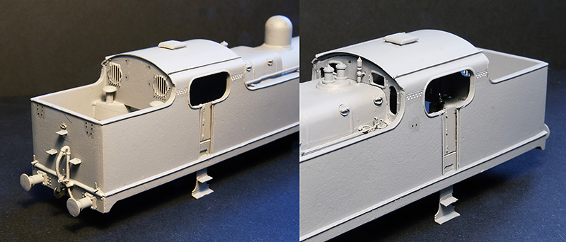 With everything in place and being happy wit the fit of things the body was given another light undercoat before the missing rivets were added from my dwindling supply of Archers along with some from Railtec. Thankfully the flatirons dot have a lot of visible rivets.
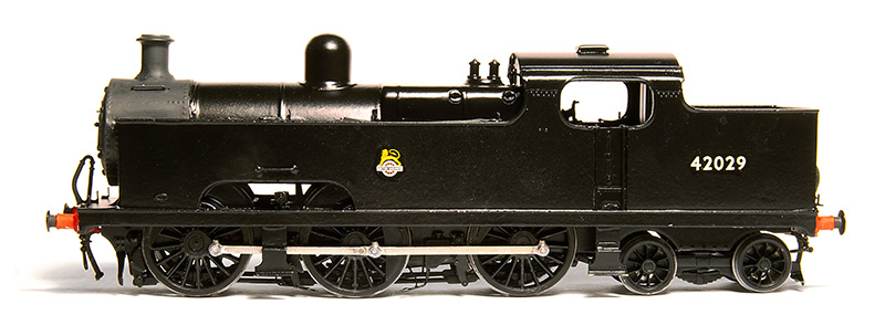 I don’t normally take a painted but pre-weathered picture but this time I made an exception. I mentioned in the last post that because of the carzatti front axle the coupling rods seemed backwards to the norm with the joint ahead of the middle axle not behind it. When No.2000 was modified this remained the case. The kit has the coupling rods the normal way round with the joint behind the middle axle and I’ve never seen a model flatiron (in either 4mm scale of 7mm scale) that addresses this. I found 52f models do a set that have the right wheelbase with the joint in the right place so I used those instead. One little tip that seems really obvious but I’ve never seen anyone mention (perhaps its because it is obvious to everyone else?) is that I line up the coupling rod on this side with the orientation of the grub screw on the final drive gear. It makes accessing the grub screw simple should you need to in the future as you know where to stop the wheels rotation.
Below some pictures of the finished loco with my usual caveat of still needing coal and a crew. 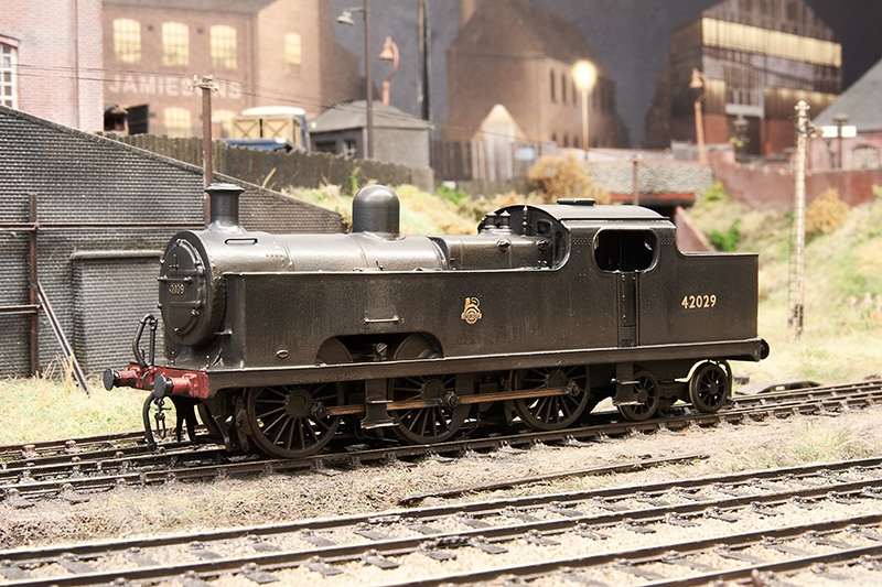
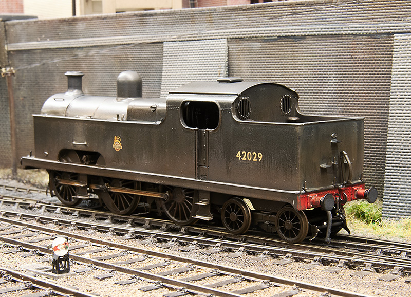
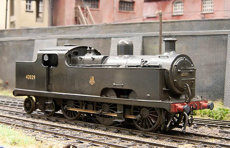
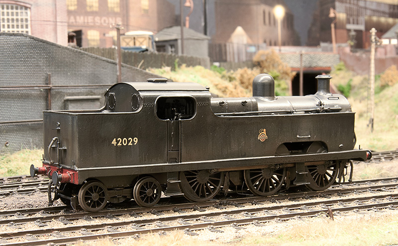
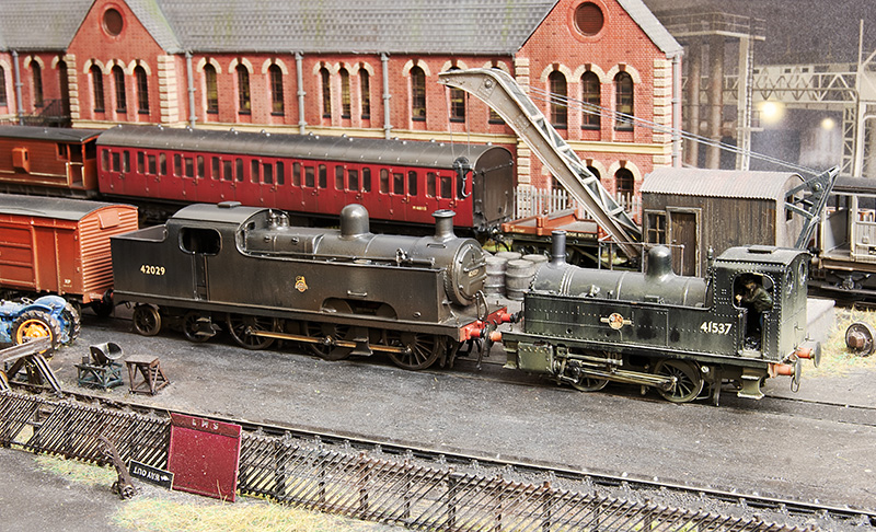 With her baby sister!
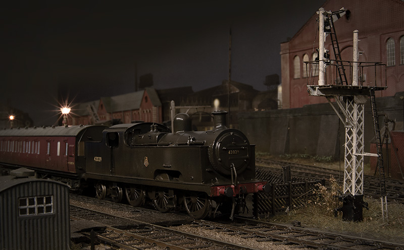
Flights of Fancy – Part 1

Long time readers may remember this illustration I did a fair few years ago. At the time I was toying with the idea of BR Flatiron for Brettell Road. People who know anything about these locos will know that they only made it as far as 1938 before the lastof them went for scrap but my theory was what if they didn’t and made it another 2o years or so? After all we are all happy to bend the historical truth when it comes to places but why not locos too?
A brief history
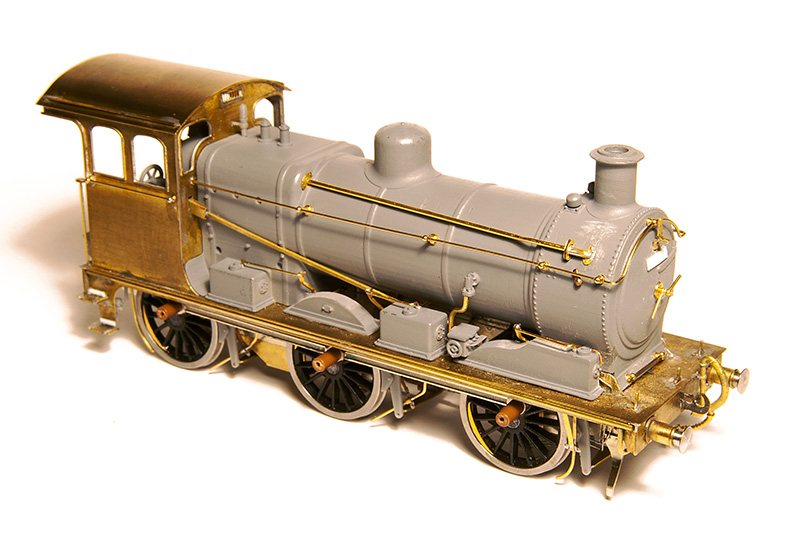
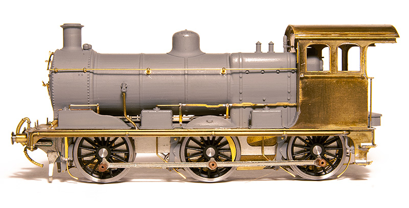
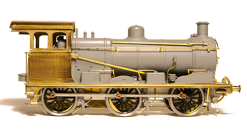
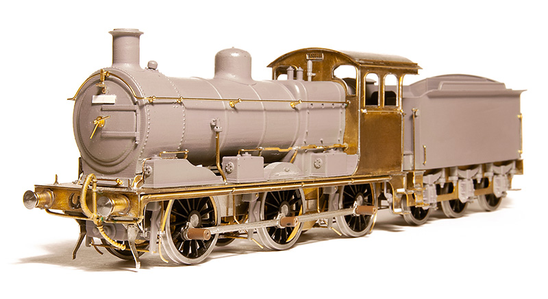
Samuel Johnson of the Midland Railway had identified a need for a large passenger tank engine in 1903 and while a 0-6-4 seemed a logical progression of their 0-4-4 tanks several ideas and arrangements were put forward both before and after the design by Deeley was settled on. These ranged from a 4-4-4, a 2-6-2 with odd split side tanks, through several variations of outside cylindered 2-6-4’s and a 4-6-4. All of the class of 40 were built in 1907. As it turned out this was not a wheel arrangement that would become at all common in the UK. The front axle was mounted into a Carzatti slide giving extra play and resulting in a somewhat backwards arrangement of coupling rod with the knuckle joint ahead of the middle axle and not behind it as was the norm.
In early LMS days the class were fitted wit new superheated Belpair boilers resulting in a different firebox and being longer, the boiler now sticking out from the front of the tanks. The cab spectacle plates were also changed at the same time.
In 1928 loco No.2015 derailed at speed near Newark and a passenger on its train was killed. 2 more derailments occurred in early 1935. The first instance was when N0.2023 derailed at Ashton under Hill in February, killing its driver. 3 weeks later number 2011 was observed by railway inspectors operating between Leicester and Burton upon Trent only to itself derail 5 days later at Moira. Fortunately this time no serious injuries occurred. But the reputation had set in, the class were well known as rough riders on anything other than perfect track and were noted to run smoother going backwards.
An idea not completely without precedent.
The case for these locos lasting longer than they did is not without precedent. Class leader N0.2000 underwent some modifications to see if the riding could be improved. These were the replacement of the front axle arrangement with traditional springs (giving a different look) and an improved bogie with side bolsters. No 2000 was tested against an unmodified classmate No.2012 which itself had recent general repairs and not yet clocked up 1000 miles since. Both locos were considered to be in first class running order.
On the first test No.2000 ran between 35 and 50 mph before selling back to 35 and it was reported that the engine rode very steadily with no side movement reported of the trailing bogie. Test 2 saw No.2000 run between 45 and 50mph settling back to 45 with the same results. Test 3 was run at 55 and occasionally 60mph and this test was satisfactory enough to try test 4 where she was run over 60mph, reaching a speed of 67 before selling back to 65. It was reported that a slight amount of side oscillation developed and a slight roll but was still considered satisfactory riding.
No.2012 ran 3 tests. Test 1, 35mph occasionally touching 40 and the riding was reported as good with a slight oscillation and roll being perceptible on the footplate. Test 2 saw 45mph with occasional 47 and the riding was considered fairly good but with more oscillation and tendency to roll. The final test saw running at 55mph with occasional 60 and the riding was reported as rough with the oscillation and roll said to be pronounced and the front end having a tendency to develop an up and down surging motion.
Although the results of the modifications to No.2000 were good Stanier decided that the rest of the class were not worth altering and between 1935 and 1938 they were all scrapped with many of the (standard) parts going on to other locos. It was reported that many of the boilers were used on 4f’s.
But what if Sanier thought the modification were worth doing to the entire class? They were only 30 years old and many midland locos lasted much longer than that. As the boilers went to other locos they were obviously good so it it such a leap to think that a modified flatiron could indeed make it into BR days with only a slight tweak of history is it?
The Model
Luckily for us South Eastern Finecast do a kit for these loco’s and I’ve had one in the stash pretty much since I did the drawing above.
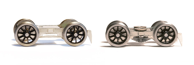
Starting with the bogie as supplied on the left and my modified version on the right. It’s been modified mechanically to provide basic springing on all 4 wheels and a basic form of sprung side control. As supplied the bogie is designed to be attached to a swinging arm much like the RTR guys tend to do. I didn’t really like that idea much if I’m honest.
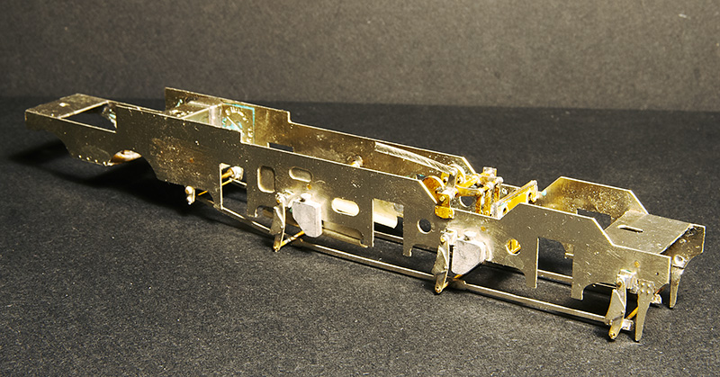 The main frames modified with some spare Brassmasters inside motion bits. I considered there was no way you would be able to see working inside motion so just modelled the bits I felt you might see if you looked hard enough!
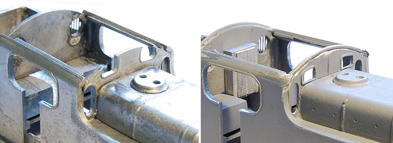
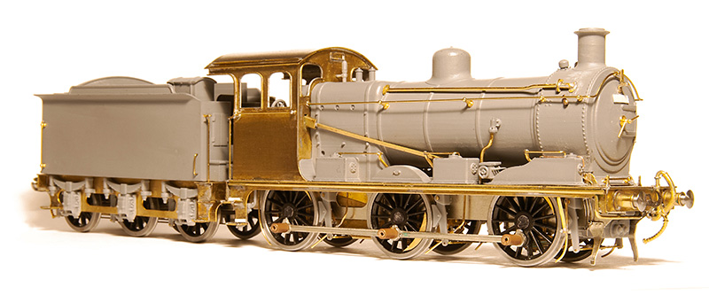
The cab Spectacle plate is a particularity weak point of the kit as it bears only a passing resemblance to the real thing, I made a new one from plasticard as can be seen on the right. If anyone wants the drawing for this (which I admit is a best guess on my part) it can be downloaded from here. The rebuilt cabs also seemed to have slightly longer roofs than the originals and little bits of Nickel strip were soldered to the corners to replicate this. 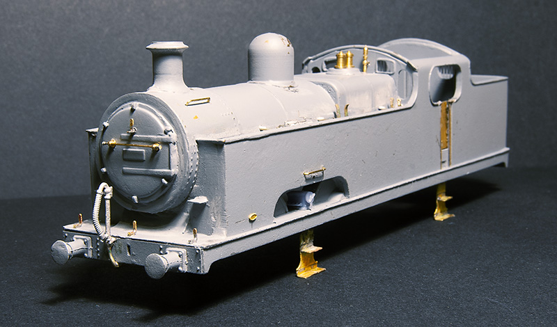 Front view. The kit relied on an upper half of the boiler/smokebox merging with the lower half which is cast as part of the tank front and this forming the front of the smokebox. The end result wasn’t all that round so I cut it back and used a 22mm copper ring in its place Buffers are from Lanarkshire Models and lamp irons from Stenson Models
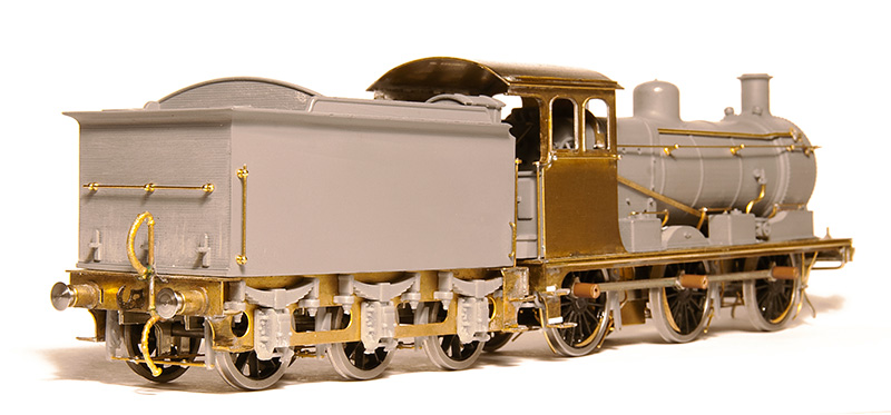
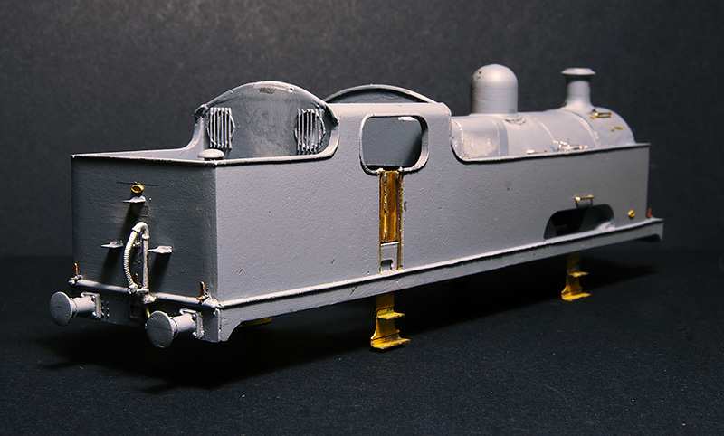 The rear view. The steps are cast into the rear of the bunker and where a little chunky. Also the top one was too low so these were replaced with some of my mk1 coach end steps. The window frames are from a Mainly Trains spectacle plate etch. Note the larger buffers on this end.
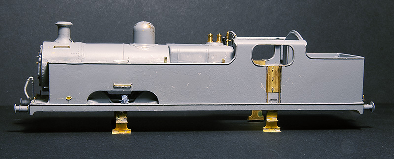
 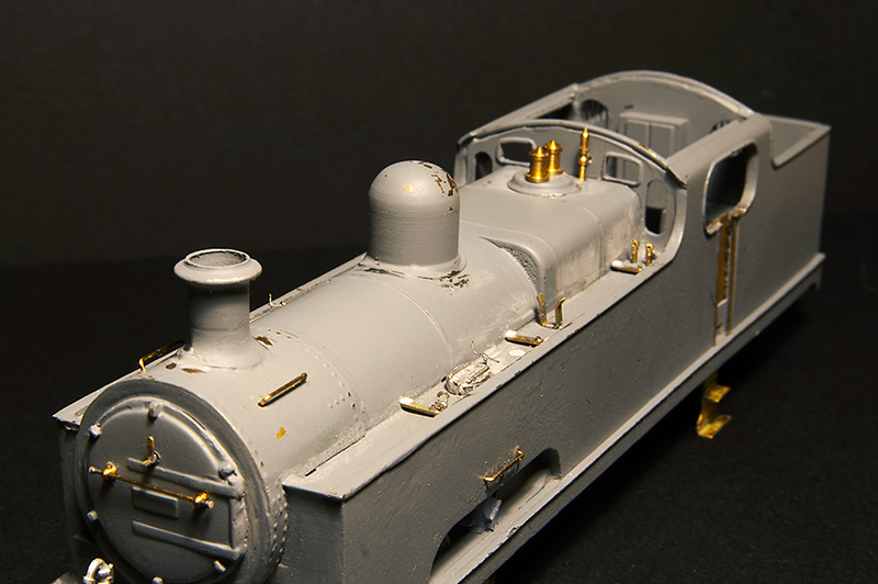 The top of the tanks are vague as supplied with just casting for the water filer caps and 2 air vents that were related to the water pick up gear. In reality only 2015 had this fitted so they should be left off all other models of the class. This is my educated guess of what should be there but i do think there should be more clutter than this. Photos of this area are rare and so far I’ve only found 2
Progress will now need to wait until after Scaleforum where i need some more bits.
Its all gone a bit Eastern Region – Part 2
Earlier in the year I showed progress on a test build of the Brassmasters J17 kit test build. What follows is progress since then.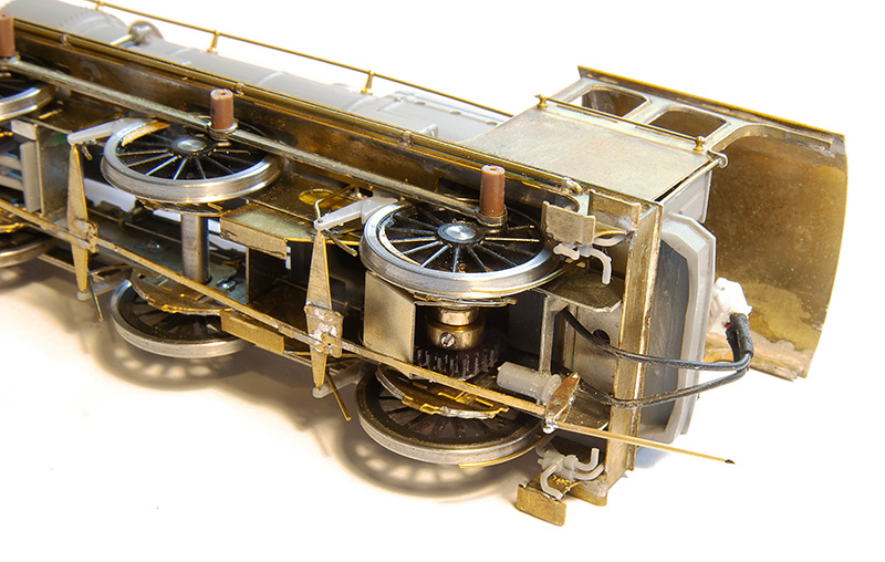
To be fair there wasn’t a huge amount left to do as I left it. One of the jobs was the business end of the brake gear on both the loco and tender. 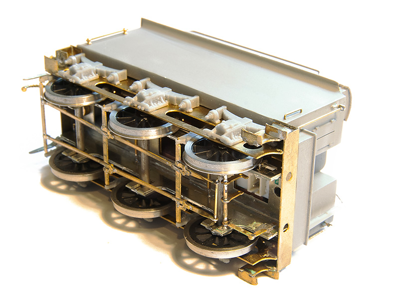
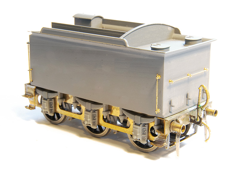 The other little job on the tender was the guard irons which had been missed off the test etch. These were fashioned up from scrap using a scaled image of the production etch as a guide.
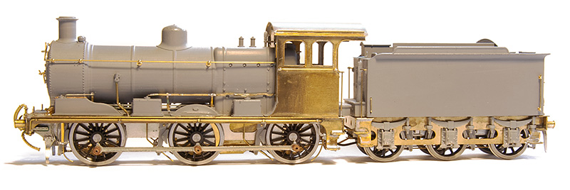
When I showed the side on view before I had managed to get the sanding linkages all wrong. This was subsequently corrected.
(Video © Tim Horn and used with permission) Then it was off to Tim’s for a few days work blocking in the basic greenery on North Elmham which was also an ideal opportunity to give the J17 a chance to stretch its legs. It was unweighted at this point except for a few pound coins in the tender. Attention then switched to getting Brettell Road ready for Scalefour Crewe and besides I thought it would be good for the loco to be displayed on the Brassmasters stand in the raw so to speak. However since then it’s now been finished off with the exception of a crew and some coal in the tender.
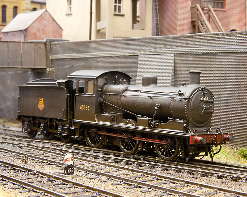
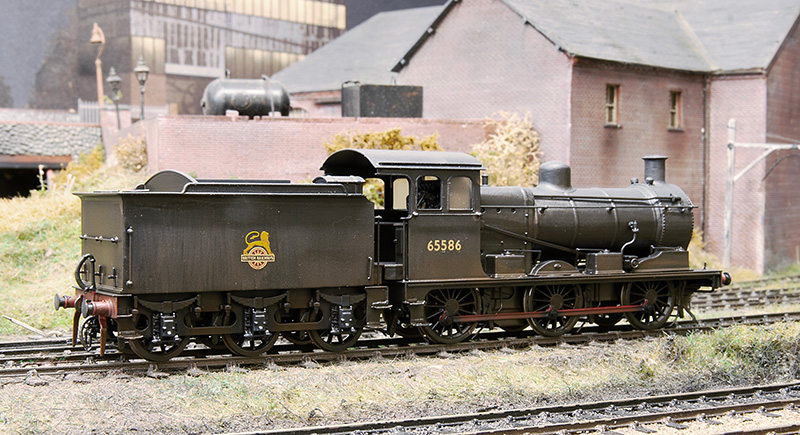
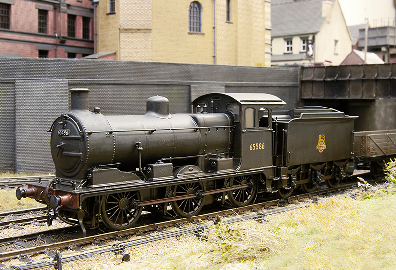
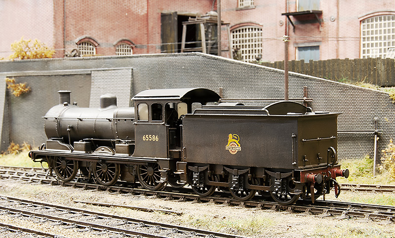
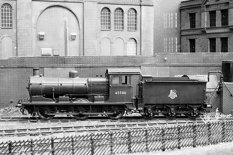
For part one of this little project click here
3F and using a Brassmasters Easychas conventionally. Part 2
Much as I quite liked the accidental JPS tribute look of my 3F (Fans of retro Formula 1 will know what I mean) My 3f has now been painted and weathered.
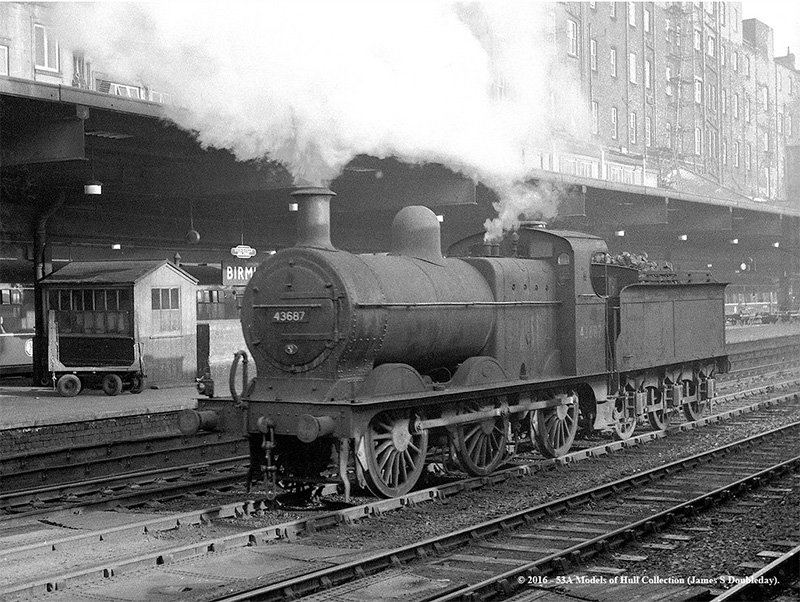 I found this image of 43687 at New Street on station pilot duties around 1957. The loco was allocated to Bournville shed at the time so it seemed suitable to me. Image ©John Turner 53A Models of Hull Collection and used with his kind permission.
Below a few images of the finished model.
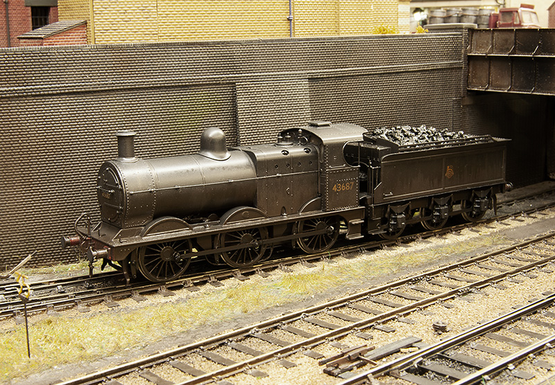
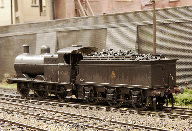
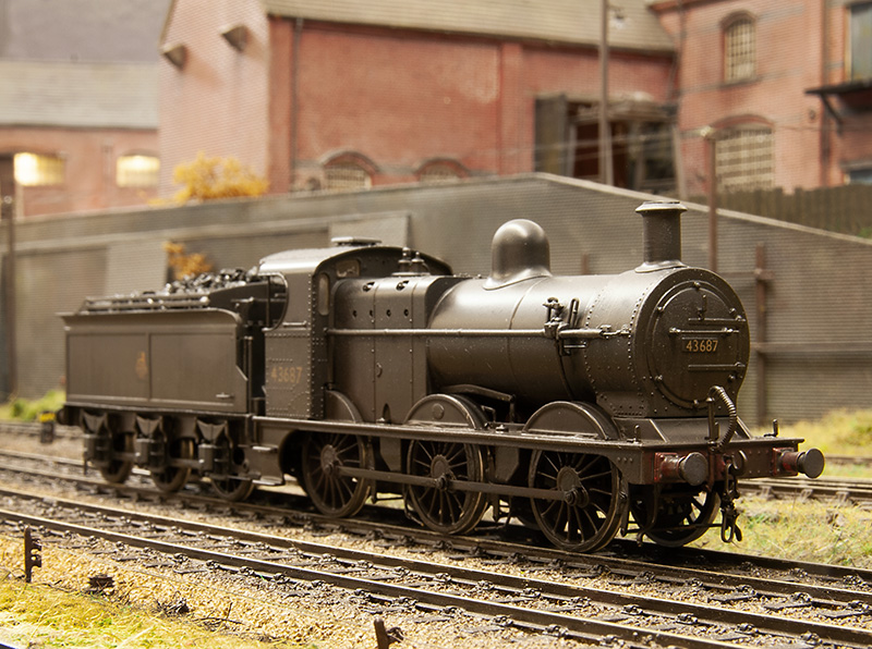
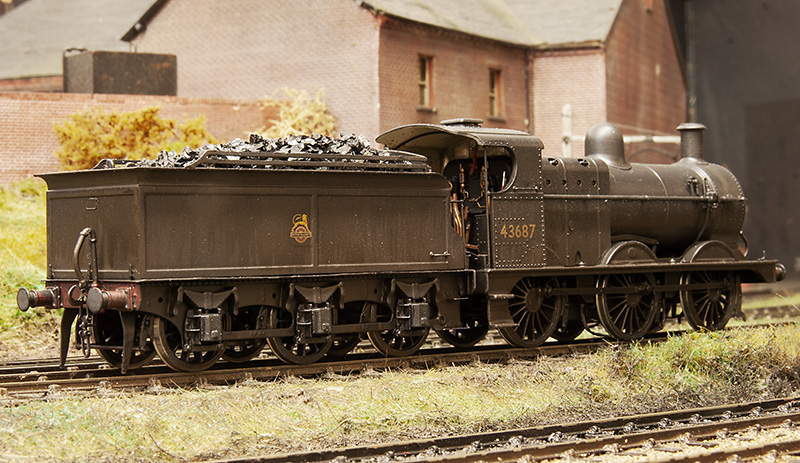
Just waiting for a Modelu crew to arrive. Does anyone know how the cab rain sheets were attached to the tender on these locos? Ive found several images of them with the sheets stored on the edge of the cab roof but none with them in use. I guess back in the day people didn’t go out to take photos of mundane freight locos if it was raining!
3F and using a Brassmasters Easychas conventionally.
Ive always quite liked the Midland 3f tender locos. They seem to be quite nicely proportioned, more so than the 4F’s that looked kind of tall and somewhat top heavy. A while ago in quick succession I picked up a Bachmann body followed soon after by a tender body and a Brassmasters Easychas for it. In the last week or so Ive decided to get some sort of progress on it.
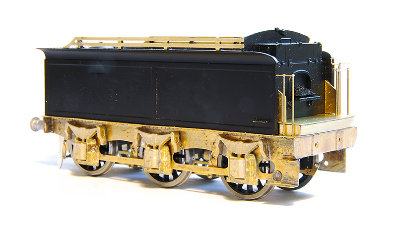 So starting with the tender. I never had the Bachmann chassis and if its anything like most RTR tender chassis it will no doubt have all been a bit flat and kinda naff. Brassmasters do a detailing kit to replace the tender chassis completely so I used that. This is just built as per their instructions.
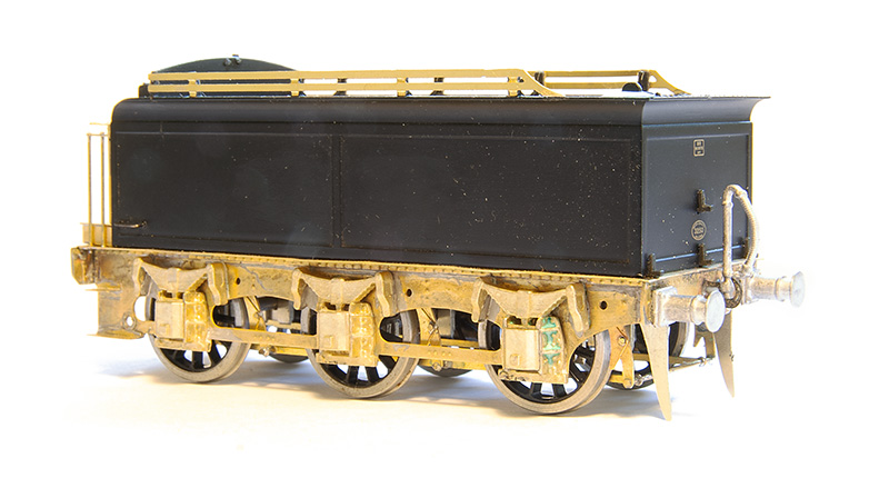 The rear end. Buffers are from Lanarkshire models as is the vac pipe. I think I’ll replace the lamp irons too.
On to the loco. If I had the original chassis then based on the 1F I did I’m confident you could have something up and running in a somewhat leisurely afternoon. If you use the Bachmann coupling rods and brakes you might not even need to fire up the soldering iron! However as I didn’t have the Bachmann chassis I decided to build the chassis up as a more conventional one by adding spacers left over from a High Level Models Jinty chassis kit. As the easychas caters for EM and p4 the EM spacers are perfect. If you don’t have any leftover Jinty bits though Alan Gibson do a neat little etch of spacers.
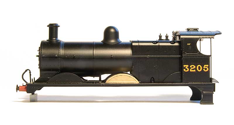 Before I show you the chassis though some decisions need to be made. The splashers suffer from the usual RTR problem of being too big. Brassmasters do a separate etch for ones that are the right size. The above image shows a comparison so you can decide if it bothers you or not.
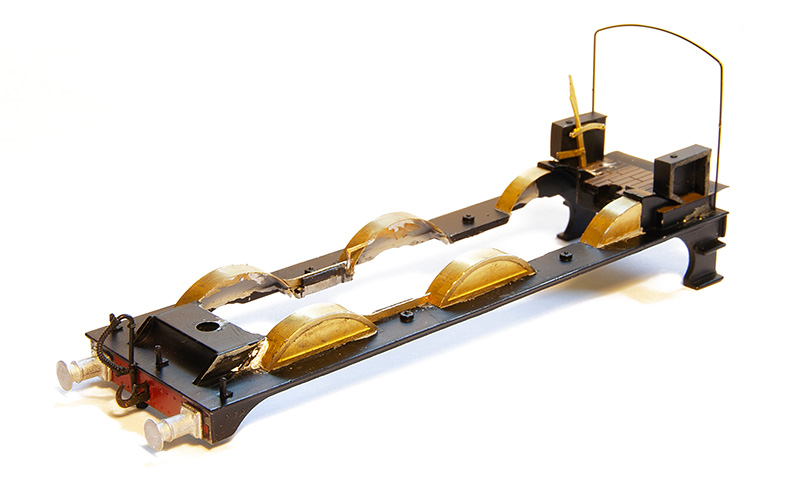 As you can probably guess it bothered me so they were all replaced. The original footplate has a solid floor back to the front of the chassis casting so I cut that out. The new reversing lever is part of the chassis kit and the boxes on the side of the cabs have been thinned down by 2mm as per the instructions.
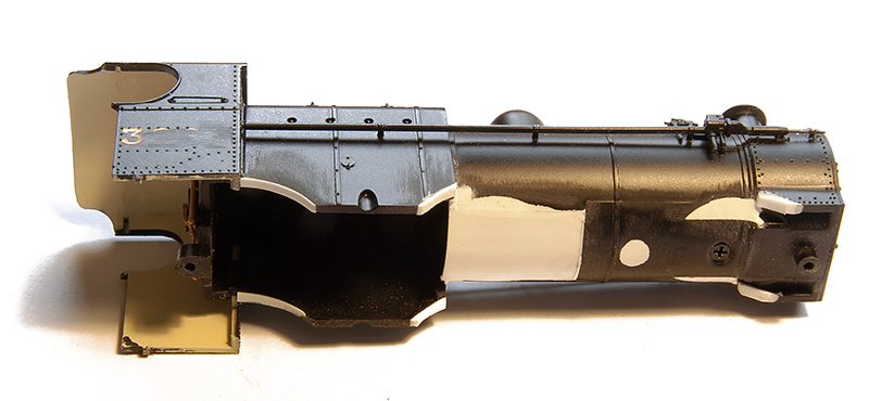 All this means that a little bit of rectification is needed on the body as it had recesses in the boiler for the original splashers that are no longer needed. I believe the Bachmann chassis block comes quite far forward so the base of the boiler was put back in using layers of thin plasticard. Theres not really much else to do to the body other than this.
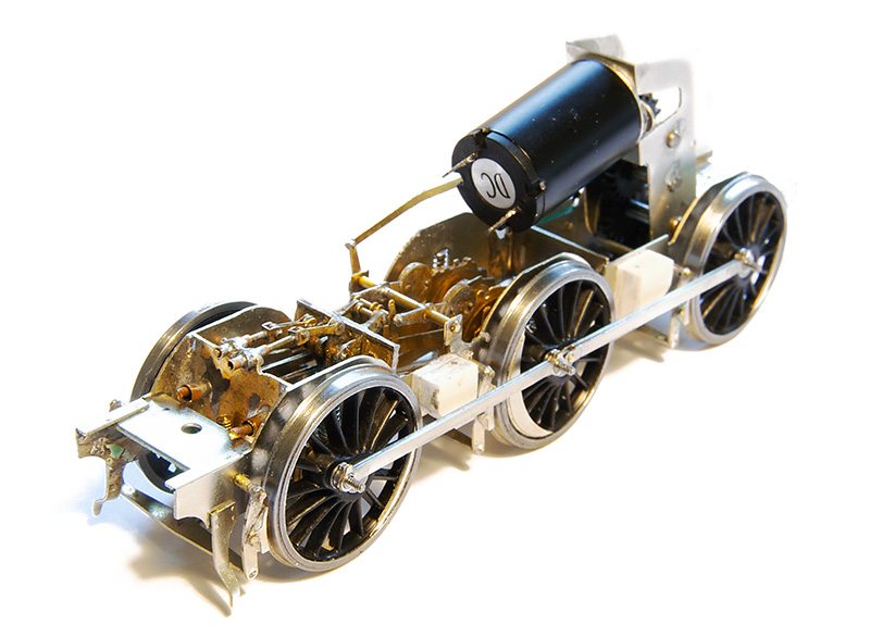 Back to the chassis then – with the inside motion kit from the 4f – You didn’t expect me to leave a gaping hole did you? The gearbox is a high level loadhauler+
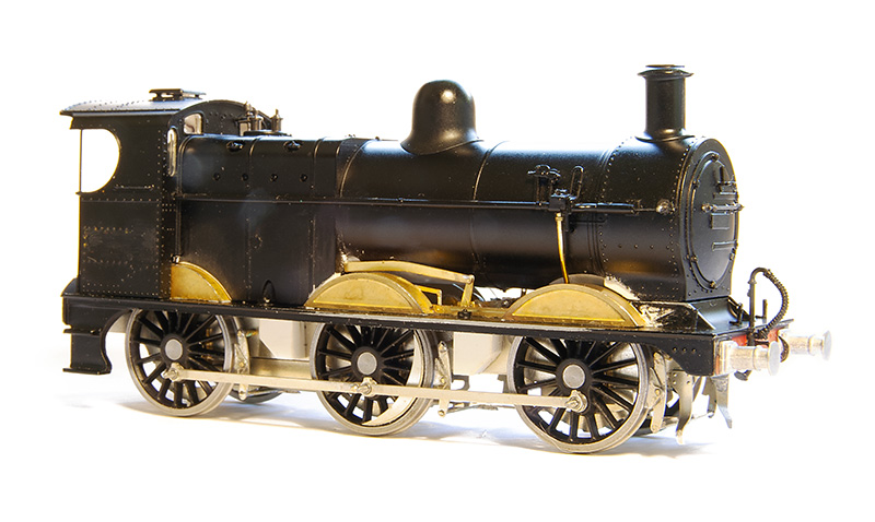
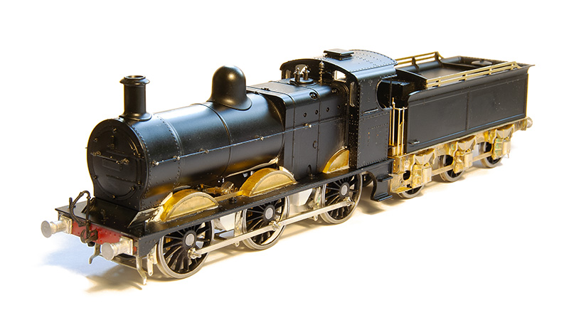
How the loco looks mocked up. I will leave the sandpipes until the very end as they will trap the centre wheels in place.
Its all gone a bit Eastern Region
Over the last week or so Ive embarked on another test build for Brassmasters. This time a J17 kit thats been designed by David Barham. Its not really any use for Brettell Road but it would fit North Elmham (which I have been know to help out with).
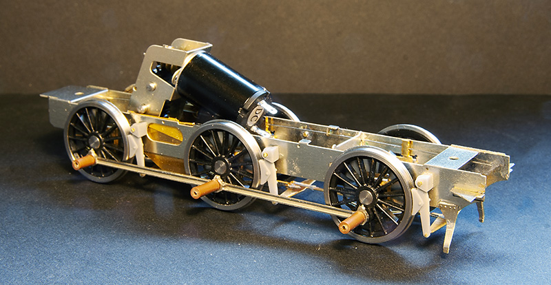
The basic chassis build with a High level Loadhauler gearbox. The loco and tender use CSBs throughout. The kit will be supplied with both printed and etched brake shoes.
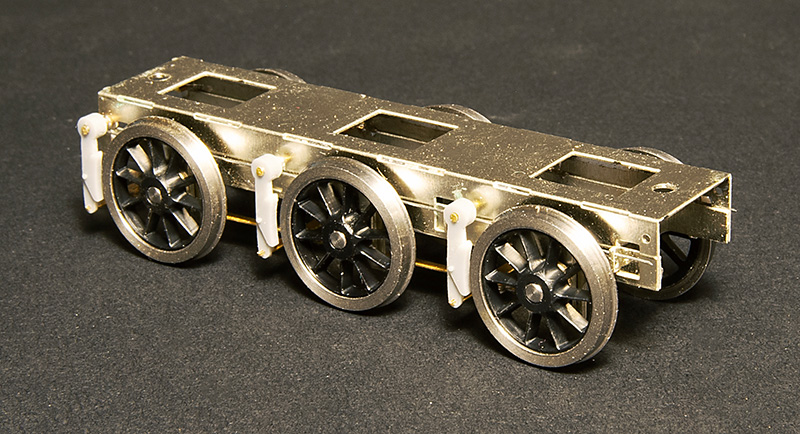 The tender subframe – Again with options on the brake shoes.
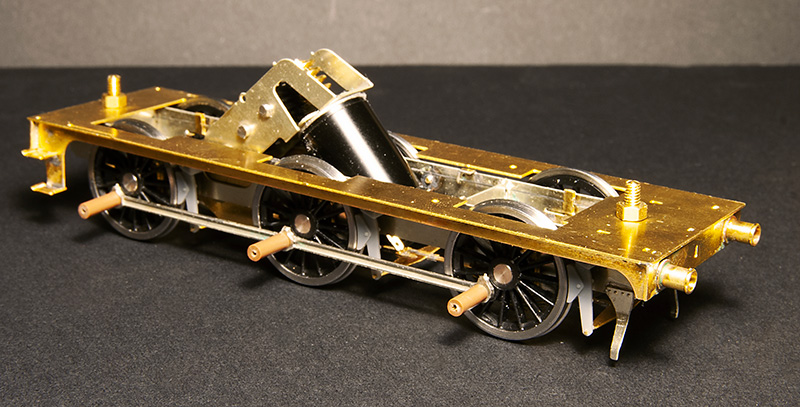 Chassis and footplate.
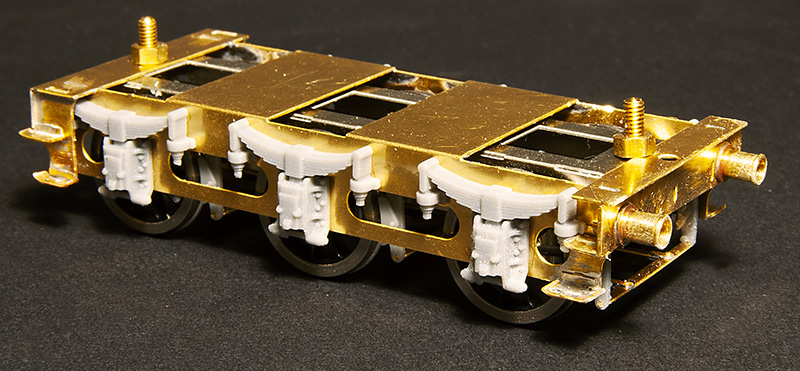 Tender with its outer frame.
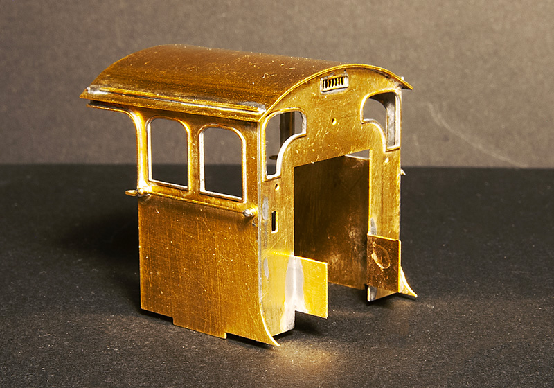 The cab
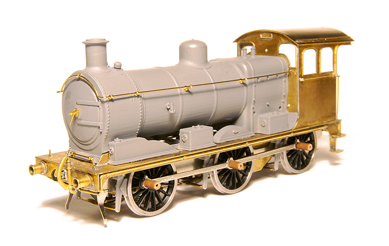 Pretty much everything above the footplate and forward of the cab is catered for by a 3D print. Here I’ve made a start on the basic detailing
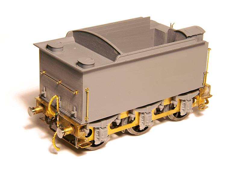 The tender body, like the loco, is a 3D print.
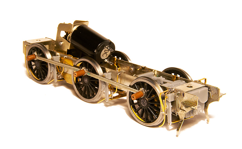
The detailed up chassis
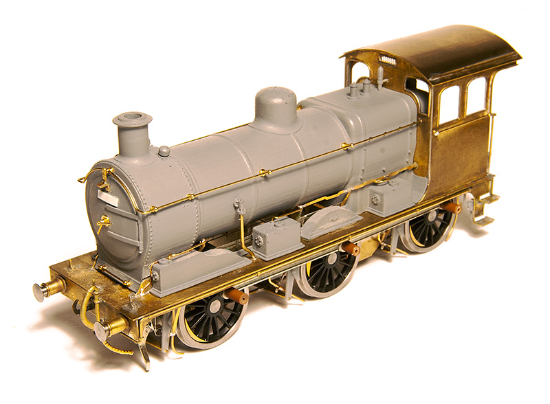
The finished loco – More pictures below. This has been a pleasure to put together.
shuffling and testing.
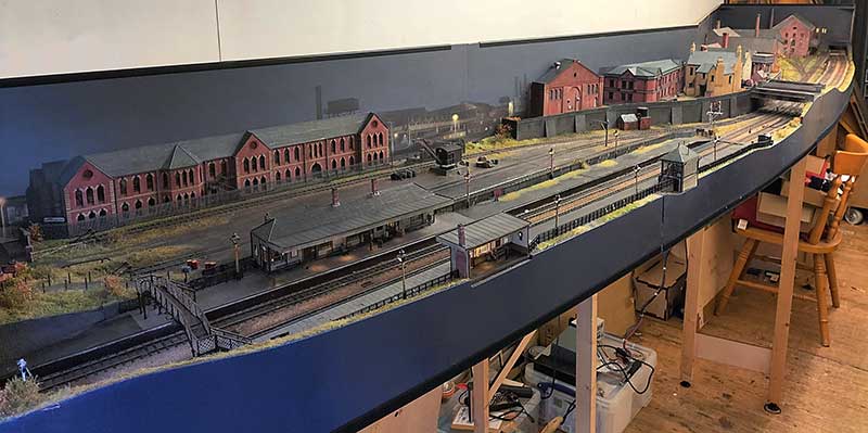
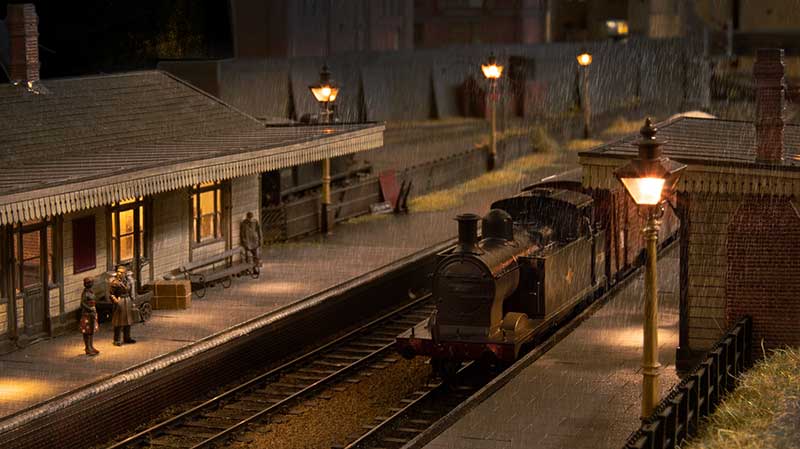
A bit of re-jigging of the shed means I have been able to put all of the scenic boards for Brettell Road up together. Its 5 months since the Cradley show – Time flies doesn’t it?
Theres a few things to fix after the show. A couple of the points needed a check over as they weren’t totally reliable. I also found 2 dead sections that hadn’t shown up during the show so I fixed those too. 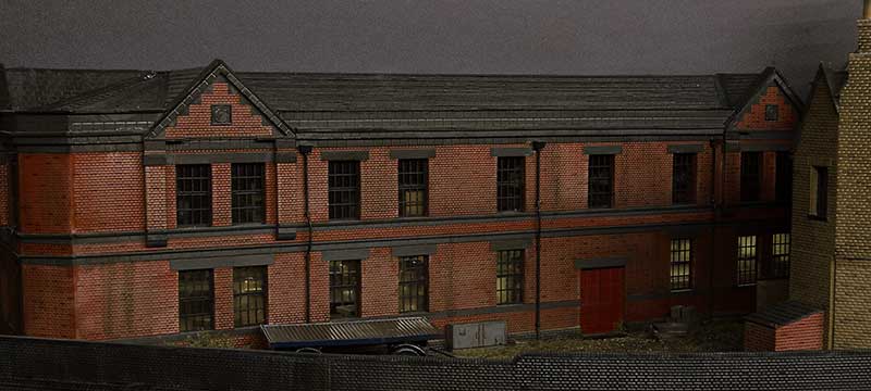 The lights on the upper floor of this building failed before the show but after the building had been planted onto the layout. It was too close to the show to fix it before so this is something to look at now I have time. I also want to add a few yard lights and sort out the telegraph poles on the layout because as they stand now they don’t make a huge amount of sense.
The other thing to fix was the route setting on the main lines. Signalling purists are advised to look away now! Before the track and signals were all operated separately via the throttles with only the yard set up as a route. (My Digitrax system allows me to program routes into it.) So thats been changed for operator convenience so that throwing a signal sets the route as well. I know the route should be set then the signal pulled rather than this way round. You can set the signals to danger on their own but in case you forget the routes will set all the other signals to danger for you anyway. I hoping this will be pretty simple to use.
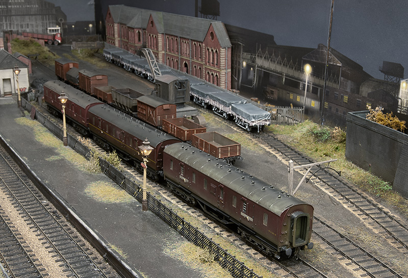 Since the show I have a small stockpile of new rolling stock to be tested. The rule is all stock must go everywhere without falling off, even though in this image only the middle road of wagons will go into the yard at shows. Of this little lot only 4 wagons were rejected and returned to ‘works’ for some fettling. These 4 have now been passed too.
Below, just some more traditional layout style pictures. 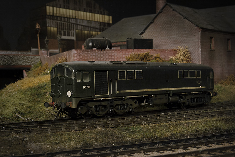
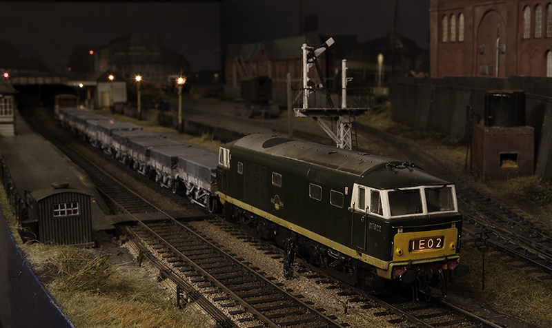
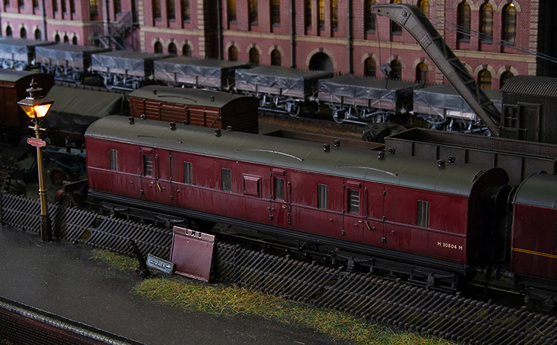
Back to the beginning (and then a bit more too) Part 2
My 2441 tank is now done. Heres some images
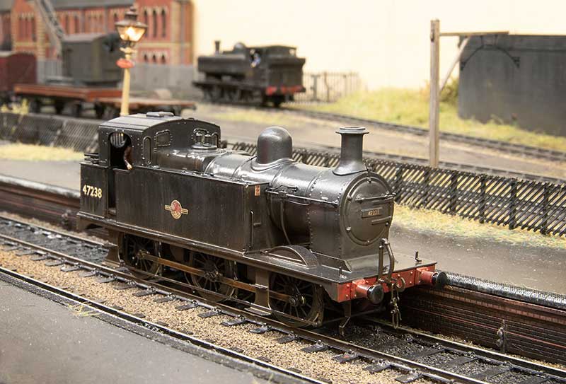 I will need to straighten that station lamp. It’s amazing how things are so obvious in a photo but equally so invisible to the naked eye!
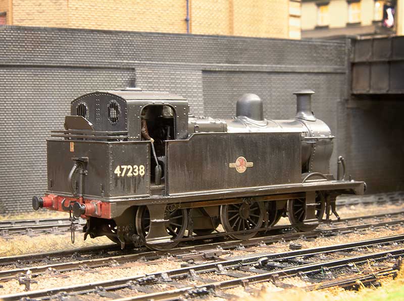
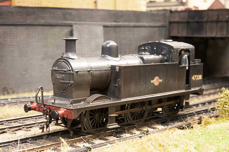 Crew by Modelu which is pretty much standard these days
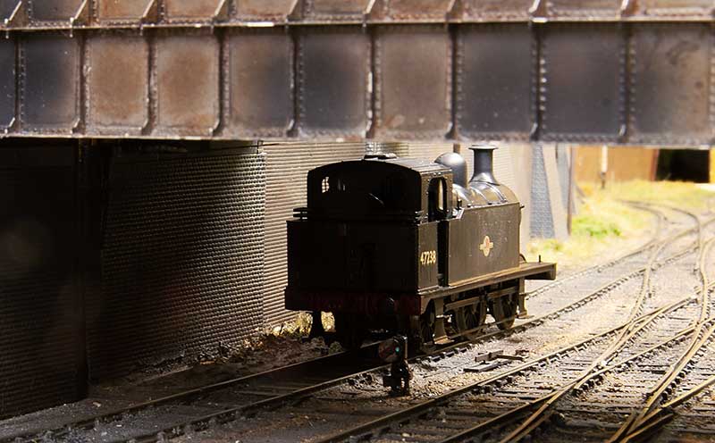
Lurking
Back to the beginning (and then a bit more too)
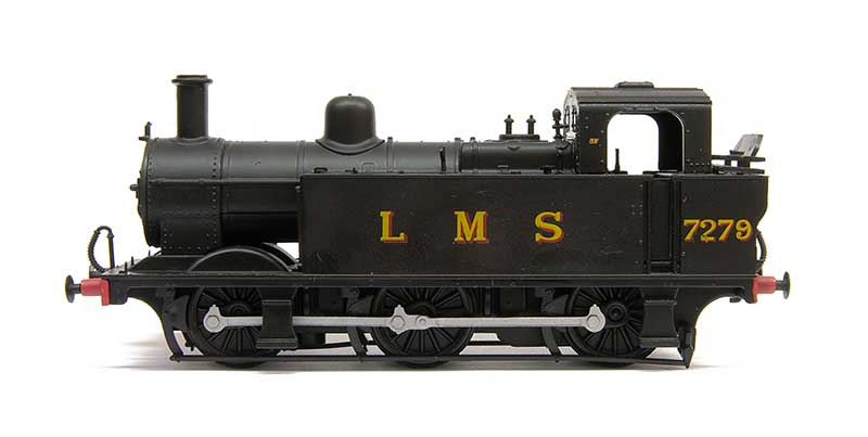 The Great British Locomotives Jinty. The model that started this whole diversion into the late 50s era. When they first appeared (as part of a magazine series) they were so cheap that I brought a second one just so I could do a before and after picture.
Recently I dug it out but I didn’t want to just do another Jinty so my focus has been on its predecessor, the Johnson designed Midland 2441 class. Just for a little bit of clarity before we go any further both classes were referred to as Jinty’s or Jocko’s so going forward, if I mention Jinty’s I mean the later LMS Fowler 3f.
So the 2441 class. The Midland built 60 of these which were considered as heavy goods tank engines. They were later rebuilt by Fowler which made them look very similar indeed to a Jinty. Initially there were 2 distinct types. with or without condensing apparatus. For those interested in these locos theres a good book on the subject, Midlands Engines No.5 by David Hunt, Bob Essery and Fred James (ISBN 1-874103-94-1)
The Model
Work required can be broken down into 2 areas. Stuff you might want to do anyway and stuff you will need to do to depict the 2441 class. Let’s start with the stuff you might want to do anyway.
The handrails need replacing as do the lamp irons. The Chimney is a bit naff as are the safety valves and whistle. The coal rail is too chunky and the buffers are somewhat generic. The steps would benefit from something a little more refined.
For the 2441 specific bits the smokebox needs to be shortened and its saddle is a different shape. The Dome is also a different shape (more rounded) although I believe some had the more flattened off type. The front splashers are different too. The biggie is the tank sides which are taller and drop down by the cab area to be a little lower than a Jinty. The bunker is also lower and squarer with no overhang. The footplate is actually a little longer on these locos and the fairing at the ends is different.
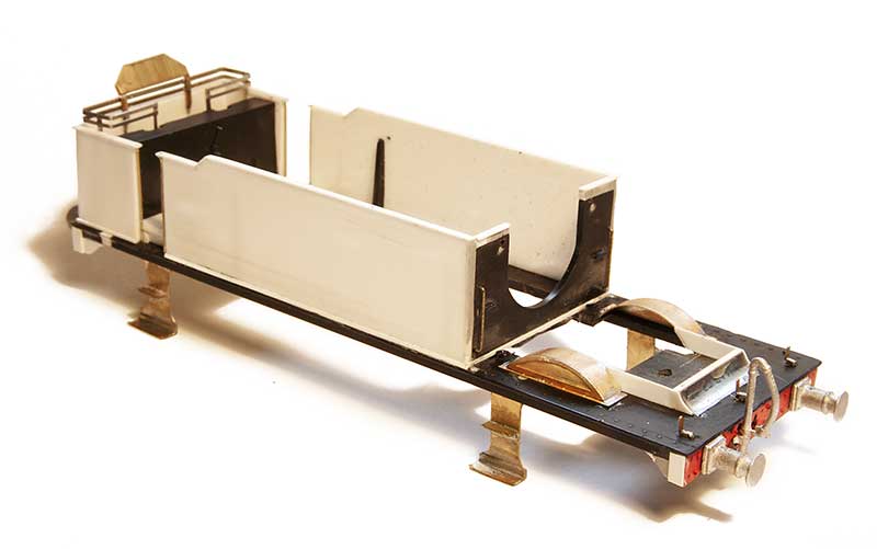 So let’s start with the footplate. The body of the model separates into 3 parts. The footplate, tank sides and bunker. The boiler, smokebox and tank tops and the upper part of the cab. Handily everything is plastic so carving it up is easy. I believe that the Bachmann Jinty has a cast metal footplate so it might be a bit more tricky.
The tank sides and bunker are from 30thou plasticard topped with microstrip. The coal rails come from my spares box (Brassmasters 1f etch) and the steps are from Mainly Trains. Splashers are also from Brassmasters (1f again) and the buffers and vac pipes are from Lanarkshire models. The lamp irons are from Stenson models. You can see at the back of the footplate where it’s been lengthened.
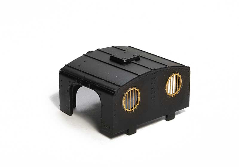 Not a lot to do the cab. New rear spectacle plates from Mainly trains.
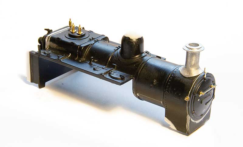 The Boiler. I cut the smokebox back and remounted the front piece (which is separate). It seems that the condenser fitted locos had the handrail below the upper hinge like a Jinty but the others has it mounted above the hinge. Chimney is from my spares box (Brassmasters Jinty detailing kit I think) and the safety valves and whistles are from Markits. The top of the dome had been filled and blended into a new shape.
When it comes to the tank tops, the drawings show the filler caps to be more central and they certainly would need to be on the condensing locos as theres a big pipe in the way. However pictures of the non condensing ones show what looks like the bracket at the front of the tank indicating that they might be at the front as seen on the model.
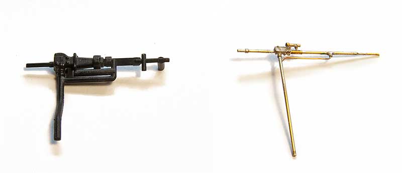 A little bit of fiddlyness for the ejectors. The moulded one is a bit clunky and I believe depicts a combined large and small Ejector. When I did my other Jinty I used a cast detailing part for this from (I think) London Road Models. Some 2441 class locos had these. The fiddly one depicts an earlier type and is cobbled together from 0.4mm wire with 0.6 and 0.8mm tubing.
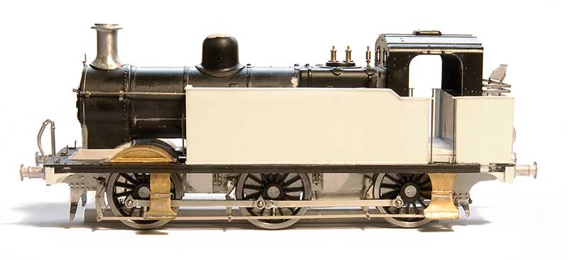 The assembled loco (so far) The chassis is a High level Jinty with the frames altered to be shallower. Otherwise it’s built as per the kit. I didn’t go for working inside motion as you really cant see it at all on these locos.
An unremarkable little tank engine – Part 2
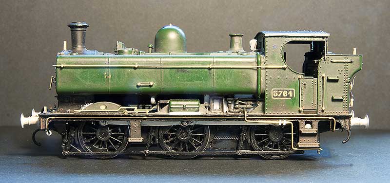
Thoughts turn to the remaining detailing on the body of my 57xx tank. I like to take pictures pre paint for prosperity before it all disappears under plain black and grime and no one really notices what you’ve done anymore!
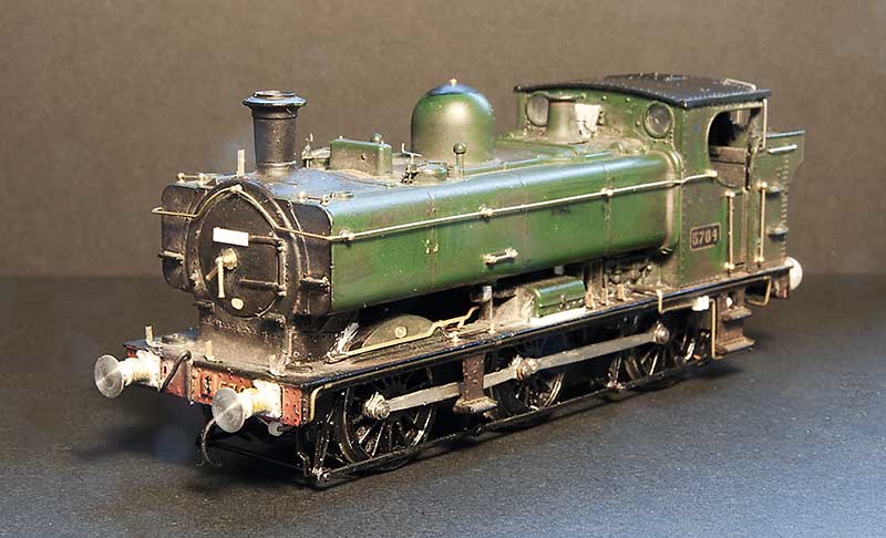 Front 3 quarter view. You will notice that the buffers are different. Due to a timely new casting arriving from Lanarkshire models. Lamp irons are from Masokits and the sanding levers from RT models.
  The footplate pipework has been replaced with wire The Whistle shield is from Modelu reinforced with a bit of wire. The tool box seemed a little ‘floaty’ as mainline had modelled it so I filled in the gap and re-scribed a finer one.
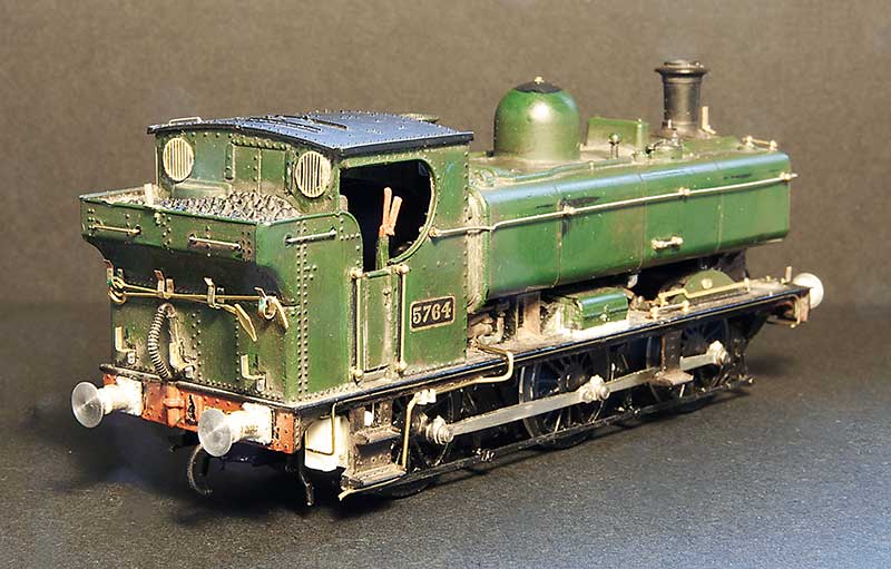 Rear view. The fire irons are from Springside Models and the rear windows from Mainly Trains (now Wizard models). I’ve thinned down the cab sides
 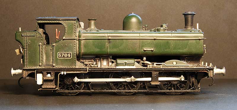 I tried to do the water balancing pipe as one piece secured by magnets but as its all a little bit small the magnets weren’t really strong enough. I had fears of it falling off and causing havoc with the inside motion so I had to settle for it being in 3 parts instead. Not sure what the little box is behind the rear footstep not all locos had them. I think it might be related to the AWS gear.
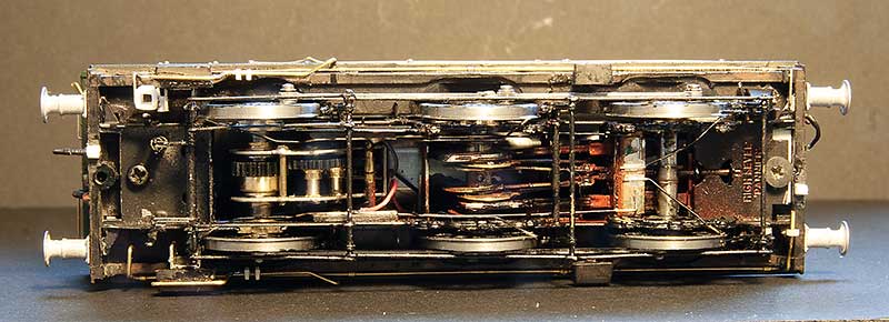
Underside view – you can just make out the way the pickups are arranged.
My intended victim for this model was 8718 which in Brettell Lane era was a Kidderminster Loco. It later went to Stourbridge where it lost its number plates and gained painted on numbers in a reasonable attempt at the GWR font. I preferred the proper number plate. Searching for pictures I couldn’t make out a BR logo on the tank sides. A request to the GWR modellers and British Railways Steam era 1948 to 1968 facebook groups didn’t yield any answers either so reverting to my ‘model what you see, not what you think you know’ approach I left the logo off.
Below a few images of the finished loco. The crew are the customary Modelu products.
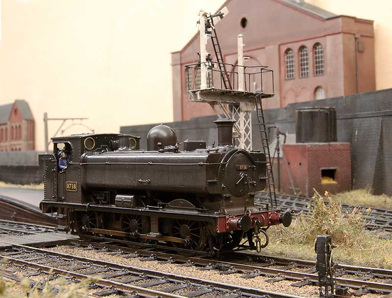
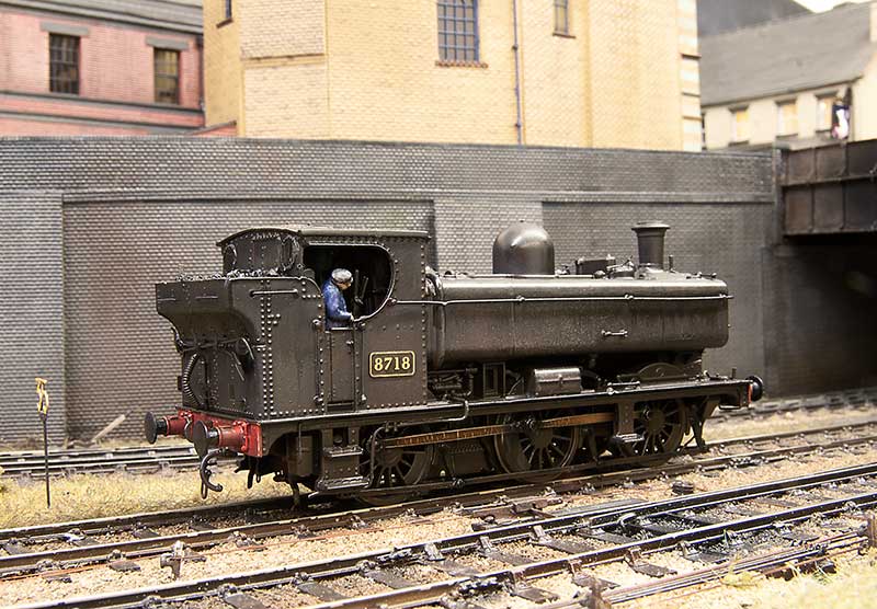
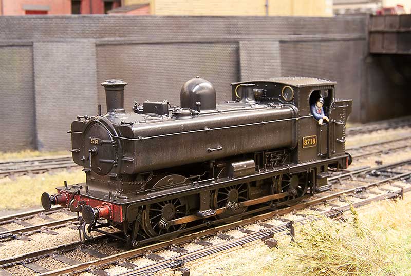
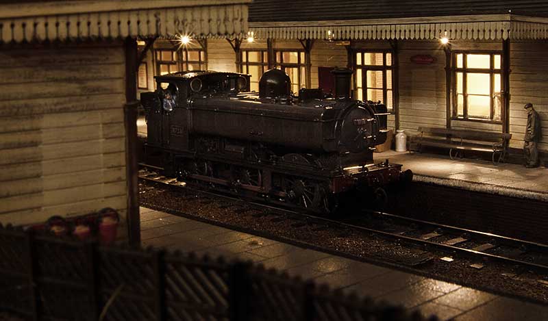
So there you have it – An unremarkable little tank engine.
An unremarkable little tank engine – Part 1
One of my slow burning projects has been a humble little 57xx tank. A combination of the old (But essentially quite good) Mainline body and a High Level Kits chassis but with a bit of twist.
Iain Rice wrote about these back in MRJ 61 and 62 using a similar route, in his case using a Perseverance chassis as that was what was available around the time, and I would urge readers to refer to this as a start point.
The High Level chassis
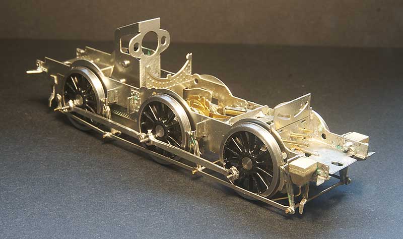 Like all of Chris’ chassis this was a joy to build (this is my 4th of his chassis kits now, who would have thought it?) I opted to use Brassmasters bearings which may have messed the alignment up a little as I found I needed to mount the break gear 1 mm lower than as supplied. Strangely though the buffer height seems fine. I differed a little bit from the instructions by making all of the brake gear removable. The rear rods that go behind the wheels seems to trap the rear axle in place as supplied.
Eagle eyed viewers might spot something little odd and yes, you’ve guessed it – I’ve gone off piste again.
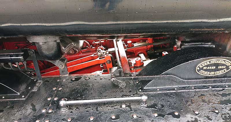
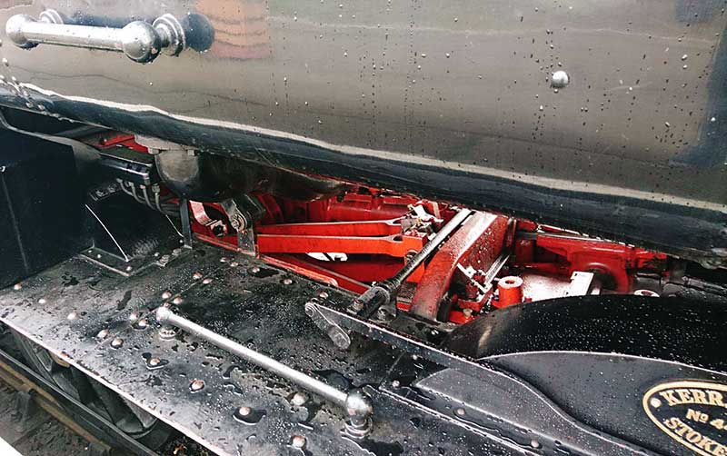 A couple of prototype pics from the Severn Valley. Personally i though the inside motion was pretty obvious looking at the real thing and while there is a representation of it in the High Level Kit I wanted it to move.
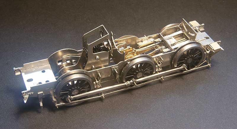 So this is a mish mash of bits – Brassmasters 4f bits at the axle end and Finney GW bits at the front. The GWR version of inside motion seems much simpler that the midland one and the hardest part of this task wasn’t putting it all together but getting it in place. Being a small loco theres not a huge amount of wiggle room.
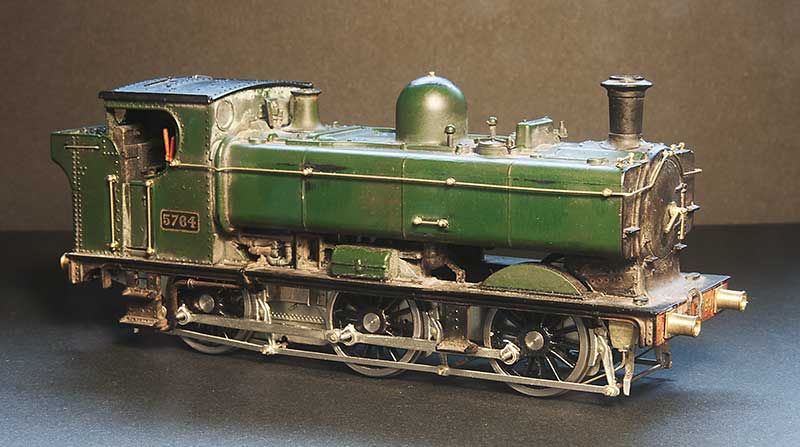
The body is essentially good, you could say extremely good for its time. The obvious stand out bit of weirdness was the top of the dome but nothing a spot of filing can’t sort out. It did come with a separate main handrail and some wire ones around the bunker but they were all a bit heavy so i replaced those along with those handrails that were moulded on. I reduced the size of the front wheel splasher by cutting it off and gluing it back on, The width of the cut being all you really need. I didn’t feel the need to fiddle with the centre and rear ones. While on my 94xx I replaced all the pipework under the tanks in front of the cab with this model I thought it was good enough as is, although I have cut away the ‘holes’ as per Iain’s article. Theres a bit more detailing to add to the footplate yet and the lower pipework will need to be replaced.
Funny little Alien
For all of my lifetime, certainly my time aware of railways, mainline diesel locomotives have been powered by a diesel engine driving electric traction motors. However the Western region was never really one to follow what everyone else was doing and invested heavily in Diesel hydraulics. Of those the largest class and the only one to fit into the type 3 category were the Hymeks of which I missed out on. When I was born there were half a dozen still in service and they were withdrawn before I had transitioned from a 4 legged human to a 2 legged one. So they are all a bit alien really.
Apart from the transmission (and the idea of a mainline loco with gear changes) there were other things that were a bit odd. Why wasn’t the radiator fan housing central? Why didn’t they use no.1 and no.2 ends, Instead of having A and B and why was the radiator at the back not the front like everything else? Despite all the weirdness they were attractive little locos though so when a Heljan one popped up cheaply on Ebay (described as having intermittent running) I put in a cheeky bit and as no one else did, a Hydraulic is coming to Brettell Road. 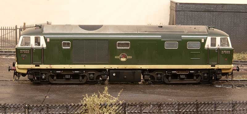 Not having any 00 track I didn’t investigate the reported running problems but the Heljan wheels were filthy and having swapped them out for some Alan Gibson ones no running issues were encountered. This model is one of Heljan’s early efforts and in terms of getting the shape right still one of their best. However there are a few tweaks that can be done. The roof horns were broken so they were replaced with Markits brass ones. The buffers were a bit naff so those were replaced with Lanarkshire Models ones. The numbers and builders plates are from Shawplan/Extreme etches. The rest is really down to working with what Heljan give you. The bodyside windows are flush glazed but not flush enough so they were cut out and remounted. The cab side and door windows are fine but I did add the droplight strips from 10×10 microstrip.
Not much to do on the chassis really – I added the mileometer on the leading axle of the B end (left) and I thought the pipework on the bogie frame at the A end was a little too fine so replaced it with wire.
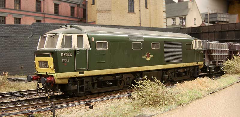 This is the A end from the other side. As I was doing an early batch loco I carefully cut off the headboard clips and touched in the yellow. The windscreens were also not flush enough but it was easier to just replace them with clear plastic cut to shape. Oddly the glazing on the headcode box (yes i know the headcode is wrong for the train) was too flush so this was replaced as well. Windscreen wipers are again from Shawplan and the brake pipes are from Hornby (the loco wasn’t supplied with any). I also remounted the tank under the bufferbeam and added a little pipework. To avoid confusion when it comes to DCC I’ve followed the diesel electric convention and set the fan end as forward.
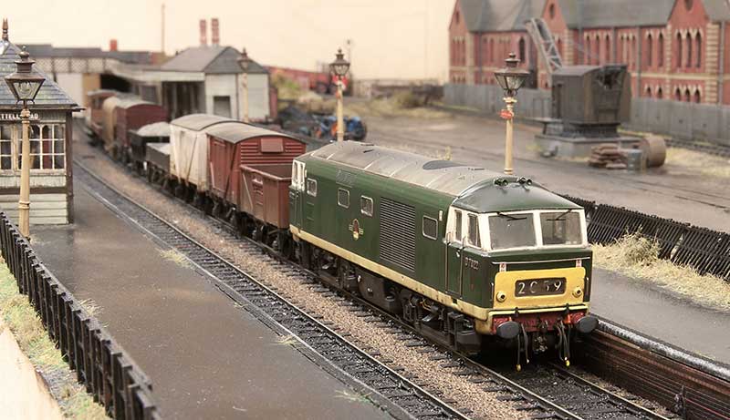 The model is weathered to look new but not 10 yards from the factory new. Im aiming for a few months and bear in mind the layout is set in autumn. There seems to be a tendency among modelers to weather Hydraulic locos to look an absolute state and most of them did end up that way in real life. So basically washes that I’ve pretty much cleaned off again as best I can before light dustings of track colour and roof dirt. This was followed with streaks from AK interactive spilt fuel and grease before finally the obligatory rain effect. Diesel locos tend to have characteristic weathering which is unique to each class (something which a lot of professionally weathered locos you see seem utterly devoid of). Class 24 to 27 have the water stain from the roof, just inboard of the fan. Class 50s have 3 leaks that run down the fuel tanks, class 20s have an odd direction for the staining deposits from the exhaust and class 31s have the oil leaks through the bodyside at floor level. Hymeks have this too but not as much and from my research only later in their (short) lives. They do however have a distinctive leak on the fuel tanks and this seemed to have been from new.
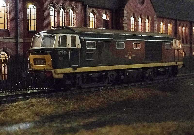
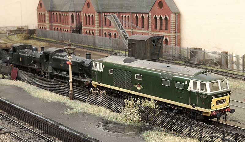 Any reason for D7022? Ive always had an affinity for the Lickey incline and these 3 locos were all regulars on banking duties over the years. The Hymeks went there much later than Brettell Road is set and were the second class of diesel to work the incline. The first being English Electric type 3s (class 37). A lot of Hymeks worked the Lickey but the initial ones were D7021-D7025. In his book, A life on the Lickey, Pat Wallace talks about them and mentioned that early on they preferred to have the A end facing north (up the gradient). If a loco turned up the wrong way round it was sent to Worcester to be turned on the triangle. He doesn’t give any detail on why this was the case but you could lock out first gear in a Hymek and the equipment cabinet for this was in the A end. The locos definitely had first gear locked out while on this duty. This was because the change from first to second gear was right in the range where trains were banked and they could snatch. The Hymeks having only one engine were a little worse for this than the Warships and Westerns.
One little anecdote Pat also mentions concerns the 17th January 1968 when a kitten was discovered in the engine room of D7025. He was adopted and named Hymek (of course). He crops up again 10 days later when he had managed to hide himself in the bogie of D7022 and refused to come out. It was reported that Hymek the kitten did 4 trips up the Lickey!
Bit of pick ‘n’ mix
Bit of a pick ‘n’ mix post this one.
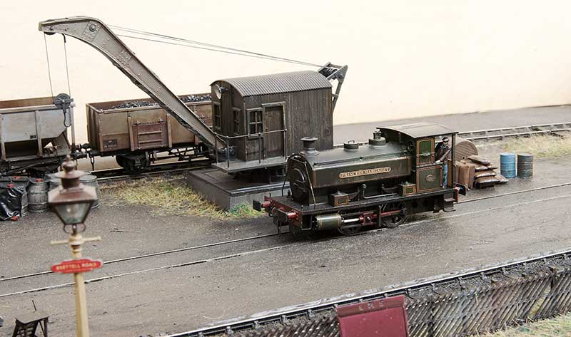 Lady Margaret now has her identity thanks to some custom nameplates from Narrow Planet
Finding your own compromise
When it comes to plastic kit building it helps if you think of a line. At one end of the line you have the kit as supplied, built as per the instructions with no attention or research what so ever on the prototype itself. At the other end you have the kit, researched, wrong parts replaced or corrected and superior parts substituted, as much extra detail as you can manage. Rumney chassis kind of thing. Inevitably we all need to find our place somewhere along the line that we feel comfortable.
This place can be influenced by several factors.
Cost – adding a lot of extra parts can mount up to quite an expensive model.
Expediency – high end models take a lot longer to build. Do we have the time
Reliability – no point adding every little detail if in use you’re going to knock it all off again.
Usage – if you wagon is part of a train of 30 that are only ever going to trundle past at a scale 40mph are you going to have the opportunity to notice the extra work?
Consistency – no point mixing highly detailed and basic kit builds together really.
Volume – how many models are we going to need?
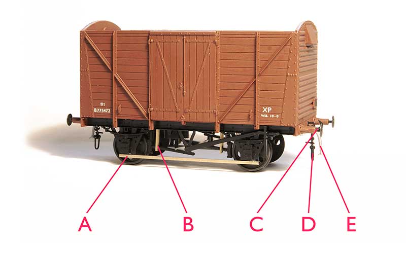 Heres my pretty much standard position along that line. The base model is a parkside kit. As mentioned elsewhere I’m not particularly worried about compensation or springing on a 10ft wheelbase wagon but i do use it for vehicles longer than 12ft wb.
A – brass tie bars. I use 0.8mm L section. the real things aren’t L section but i use this for strength and you cant tell unless you turn the model upside down. In plastic kits the tie bars are a real weakness ad they are either bendy, get broken or to avoid those 2 things, massively thick.
B – break hangers from Bill Bedford – It doesnt take much to add a little finesse to the brake gear and trick the mind into thinking its all a bit more refined that it actually is.
C – metal buffers, or in this case metal buffer heads. Unless your kit comes with metal buffers already lets be honest here, the plastic ones are going to be awful. These are MJT buffer heads.
D – couplings. A whole discussion on compromises in itself. In my case I use Smiths which i know are overscale but they are (quite) easy to use in operation.
E – brake pipe from Lanarkshire models.
Glue
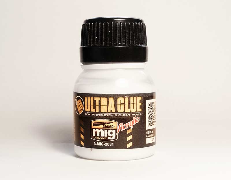 Ive recently been trying this stuff. Ultra Glue from MIG for etched and clear parts. Its water based so can be thinned if required and so far it seems to do the job at least as well as superglue. Its especially good for fitting name plates as while it has good grab it takes a few hours to fully harden and being water base any that creeps out can be lifted off with a wet paintbrush.
Reading
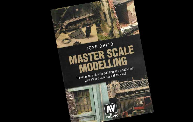
It’s been an awful long time since Martin Welch treated us to his ‘bible’ the art of weathering. And while still essential reading things have moved on a bit, especially so in the last few years or so. Some of the paints Martin used are no longer available (Humbrol tarmac for example) but theres a whole market now of weathering paints and materials. This (rather large at over 500 pages) book is an excellent window outside of our sometimes a little comfortable railway world.
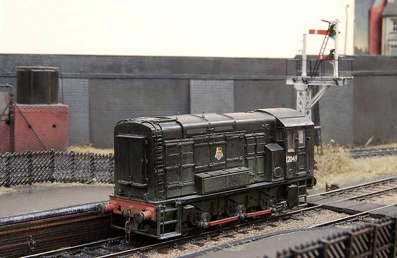
Having had a little trundle to Stourbridge shed and back for some Diesel, Class 11 shunter 12049 waits for the nod back into the yard at Brettell Road.
Hattons Barclay Tank Part 2
One change since the last post on this little tank is I’ve replaced the tantalum capacitors with a Lais stay alive unit on the recommendation of Nigel Cliffe. With this little motor I’ve now got about 4-5 seconds of off the juice running which is a big improvement.
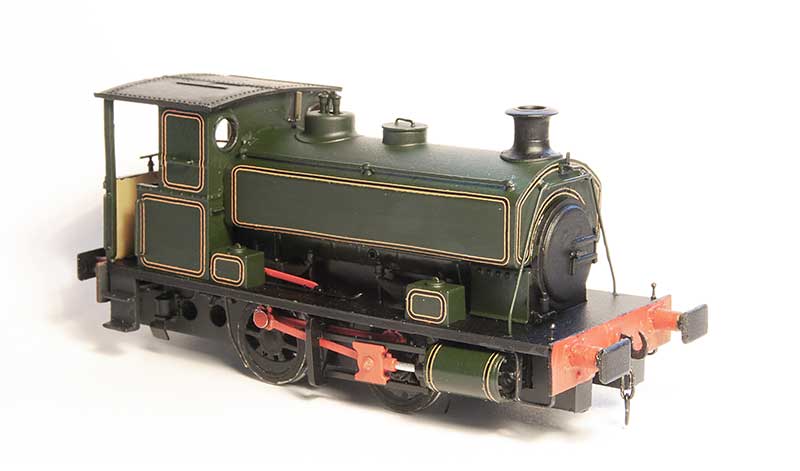 The model has been finished and lined with Fox transfers lining. I just need the number plate and name which is on order with Narrow Planet. I decided to take a quick shot of it for prosperity before i covered it all in goo!
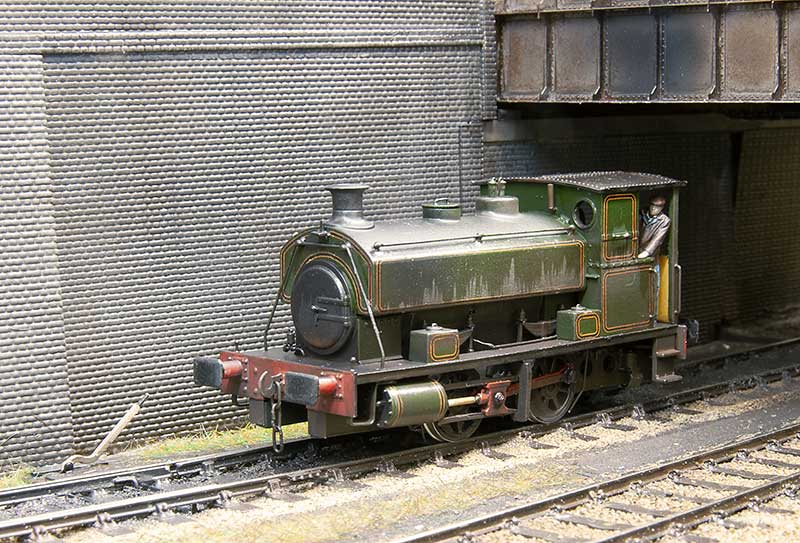 And post goo!
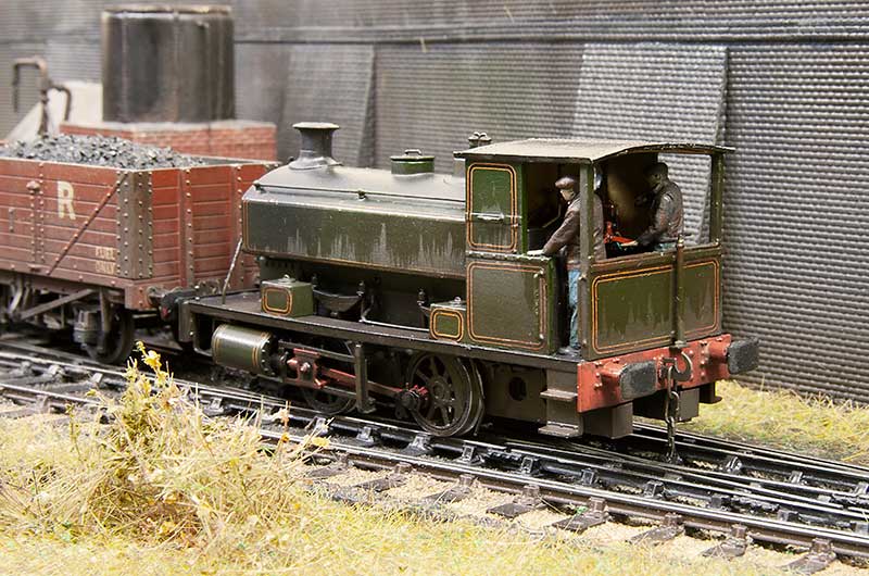 The crew are, the almost customary now, Modelu Figures
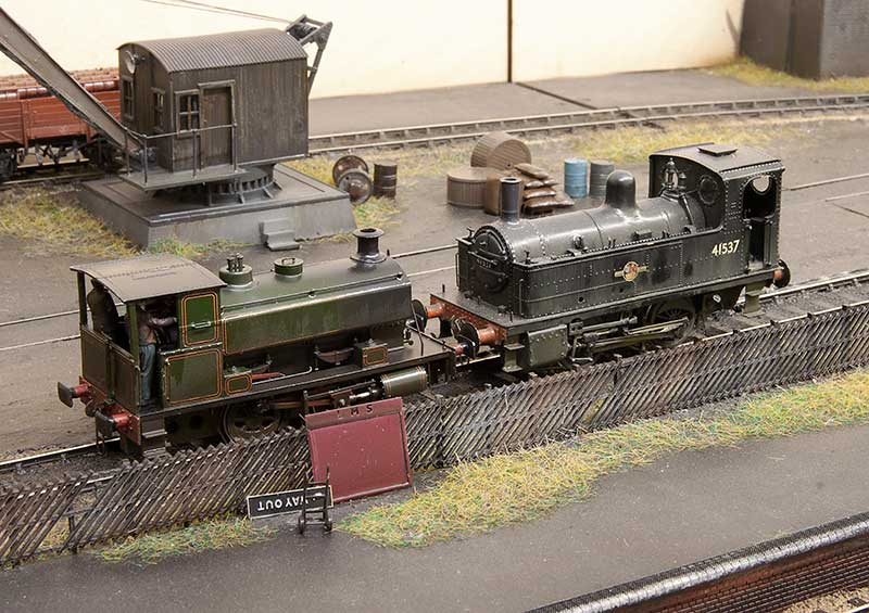 I used to think my Deeley was tiny!
Old stuff
While I’ve been in a brake van kinda mood I finally got around to improving an old Hornby LMS 20ton version I had and making it a tad more suitable for Brettell Road.
Pretty basic detailing job on this one.  A selection of Midland versions.
 Actually this brake van originally came from the Amlwch layout along with the above 47 and 24. Of the three the class 24 is as it was brought. the 47 having been brought a bit more up to date (well 1987 anyway). I wonder if Amlwch is still around somewhere?

Bit of a different angle. Let’s call this train an internal user?

Haven’t done a rainy pic for a while. NBL class 21 nestles between another pair of type 2s.
Just the simple things.
Sometimes it pays to drop back a gear and just do a few simple things that are not too taxing. Things like a few simple wagon kits or just some pictures.  And what could be more simple than the good old Airfix mineral wagon kit? This ones been converted to a diagram 102 variant and weathered with gouache and a hint of AK interactive weathering pencils for the rust.
  Next up a mix and match of parkside bits to produce a Hybar. The rail itself is a neat little etched kit from Rumney Models.
Below a few pictures.


Compound finished off.
So back to the Bachmann compound then.

The body looks pretty much spot on to me and the firebox Bachmann had modeled suits the loco I have chosen to do. 40925 was a late survivor and based at Bournville so that’s local enough for me. I added the lifting points to the front frames and the large pipe coming from the smokebox. This is an exhaust steam injector and not all compounds had them. As far as I can tell they were only fitted on one side, that being the side opposite the driver (compounds came in both left and right hand drive versions). The smoke box has been painted in Revell no9 and the difference looks a little stark at this stage.

The ejectors are the Bachmann ones cut down, again refer to a pictures of your specific loco as these varied a lot. There’s a connecting rod that appears to go from the back of the ejectors to somewhere near the slide bar support bracket. In the pictures that show this well it always looks extremely close to the face of the rear bogie wheel. I decided the best way to replicate this was to mount it on the actual bogie instead.
 Crew from Modelu – the driver looks distinctly uncomfortable straining to see. As the compounds had very large cab roofs I haven gone for a rain sheet on this model.
On to the tender

The body Bachmann supplied was a later Fowler type with coal tunnel and doors. Of course the loco I had picked had the earlier type without them. Luckily Brassmasters do a conversion kit and coal rails so that was what I used. The floor in the Bachmann model is flat so I knocked up the coal chute from plasticard. Incidentally the supplied handrails are absolutely fine and don’t need replacing. They had to be on the one side for no other reason than I mangled it!
So the model has been weathered (to look tired but not scrap line) and aside from the wheel balance weights I can call this one done.


A slight diversion

One thing that’s always bugged me a little about the above image is the coupling rods on the class 11 (left). I cant remember why but I used the Brassmasters standard rods rather than their finescale ones. Well I finally got around to swapping them over.


Another little distraction is this Bachmann anchor tank wagon.

A simple wheel swap with a new etched discharge wheel and new ladders from Stenson models.

A bit more of a ‘proper’ project was this diagram 1/163 iron ore hopper from Wizard models. Quite a neat little project this one.

Finally, i don’t want to remind anyone but the nights are drawing in again!

The Bachmann Compound – part 1
I found a relatively cheap Bachmann Compound recently and thoughts have turned to what to do with it.
Lets start with a little disclaimer. Alan Gibson supplies a set of wheels to convert this loco to P4 and I would have every confidence that just swapping the wheels would get a p4 steam loco up and running pretty quickly. After all a 4-4-0 has got to be about the best case scenario you could really ask for. I didn’t try it myself but we’ve had a wheel swapped GWR Grange (I think) running on Moor Street for years now.
Being relative new to RTR steam locos, this is actually my first RTR tender loco I’ve had since i was a kid, there’s always 2 areas that stand out to me as looking a little weak on pretty much all RTR steam locos. No, not the wheels although big, in your face, wheels do perhaps yield the greatest benefit of swapping to p4 visually. The areas I am talking about are bogies and tenders. More specifically in the case of the latter, tender underframes. They just always seem so, for want of a better description, flat!
The bogie

So to the bogie. There was nothing about the supplied RTR one that i wanted to keep so its a straight swap with a Comet example. As supplied they can be built with central springing for side control but no springing on the axles. Setting some simple springs up however couldn’t be easier.
The loco chassis

To the loco. I decided I wanted to use some of the Comet chassis bits but not exactly as intended. So the first process was deciding what of the RTR offering I wanted to keep and what I wanted to replace.
I wanted to use the sideframes in a sort of Brassmasters easychas inspired way and keep the original Bachmann drive. Initially I thought the crosshead was just an RTR bodge but they do actually look like that. So that and the cylinders were keepers. I also liked the brake gear so that stayed.
The Comet chassis is not designed for this model and is too long. The wheelbase between the driving wheels and hence the coupling rods are also too long. Comet do specify this is the case on their website. The Bachmann frames are actually the right width at the front of the loco but narrow from the cylinders back to accommodate the 00 wheels. The cylinders look, from underneath that they might fit on little pegs coming down from the footplate. They don’t, they slot sideways into the chassis. Its best to pop them off and keep them safe.
I decided to split the chassis behind the forward step to loose some of its extra length. The front part being a relatively easy fit. The rear part needed some trial and error to cut away little sections to get it to fit. The Bachmann model is driven on the front driver ( it looks like the chassis was designed for gears but to both axles but it doesn’t have them), so the Comet chassis was carefully titivated so that the rear axles position matched. I wasn’t too worried about the front driver as I has decided to keep it rigid.
By leaving the RTR style bearings off the rear driving axle you get a little room for vertical movement. A Brassmasters sprung bearing was modified with a bit of tube (the Bachmann and hence Alan Gibson axles are an odd size). The frames were glued in place using 60 thou plasticard to space them out to something more prototypical. The springs are part of the RTR keeper plate so they are too to far back but I decided to leave them as is.
The brake gear needs a bit of modification to fit over the new frames and it was here that I hit a little unexpected snag. Bachmann use bigger wheels than scale. I wonder if this is because its a development of the national railway museum model which being an earlier example had bigger wheels? Anyway the effect of this is the brake gear sits too low and would likely hit the rails when crossing pointwork. The solution is to take a mm out of the top of the keeper plate so that everything moves up a little.
Valve gear
Lets be honest RTR valve gear is generally a bit weird. Its often both too big and to thin at the same time. The Bachmann coupling rods are about scale height (ignoring the bosses which are huge!!) but being only 1 piece of metal aren’t thick enough. So these were discarded and the Comet ones used in their place. Suitability shortened by 2mm.
The connecting rods as supplied are quite good though. Much more meaty and they feature the big square bosses that the Comet ones don’t, so hybrid valve gear it is then! The Bachmann crank pins are 2mm wide (really!) so a bit of tube was soldered in to make them fit the Gibson crank pins. While I was at it I made another 2 collars for the trailing driver a the coupling rods on a compound are outside of the connecting rods.
On to the tender
Body great but underframe – ugh!

Luckily Lanarkshire models do a replacement chassis kit for a Fowler tender. This was assembled as per the instructions. For the outer frames I was kindly supplied a spare etch by Brassmasters and mated this with some Comet springs and axleboxes. I decided to keep the Bachmann steps as they are moulded as part of the tender body.

As is often the case with this sort of stuff, the most pleasing view is the one you wont ever see!


A somewhat unfocused post.

Something that always bugged me about my Heljan class 27 was the somewhat odd buffers. A long time ago i got a set of replacements from Sutton Loco Works and its just one of those things I never quite got around to. Well now that little job can come off the list.

Finished the roof of my station building – just need a layout to plant it on!

The gutters are a recent introduction from Modelu. I found they don’t like superglue at all but stick very nicely with liquid Poly (in this case Tamiya extra thin).

Popped back to my Kirtley to pick up a few things that irked. The loco to tender gap has been tightened up a bit and the rain cover tidied.

Crew from Modelu

Bit more off a proper project this one. A clasp braked 16 ton mineral from a Parkside kit on a Rumney Models underframe. The only down side to Justin’s stuff is it looks better not painted! A few pics below for history.


A quick win, relatively speaking.
With my ongoing Duchess build my thoughts turned to a little quick win project (also with Scalefour North coming up at the end of March). I said relatively speaking in the title because a few years ago I would have likely considered this quick win as a bit of an undertaking but there you go. When we were at the Wakefield show with Moor Street, my attention was drawn to a cheap Lima GWR small prairie tank loco. They were not common at all on the Stourbridge to Wolverhampton line but their larger sisters, the Large prairie were somewhat a mainstay of the line.
I know Hornby are doing a new model but a dirt cheap Airfix example was found (none runner) along with a comet chassis and I set to work.

Stage one – body detailed and the chassis built. I modified the pony trucks a little and sprung them using a method outlined by Dave Holt (see here). The original smokebox door was too small and a few extra details were added to the body. After this picture was taken I also reduced the height of the safety valve bonnet.

A quick blast of grey primer and a liberal(ish) dose of archers rivet transfers and the body was read for the paint shop. A few images of the finished result follow.


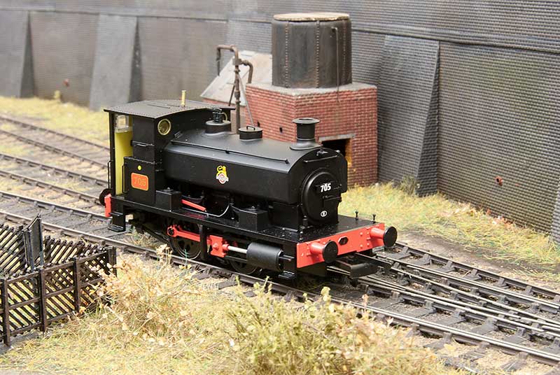 I never really intended to go for the little Hatton’s Barclay tank despite the Earl of Dudley’s railway having quite a few of them. But one popped up for a reasonable sum on ebay with a best offer option. As it would be a nice to have I put in a cheeky offer and the seller accepted it!
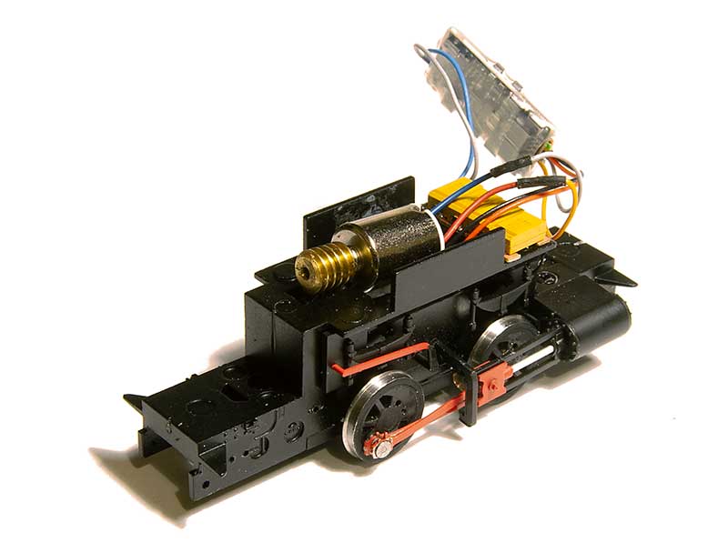
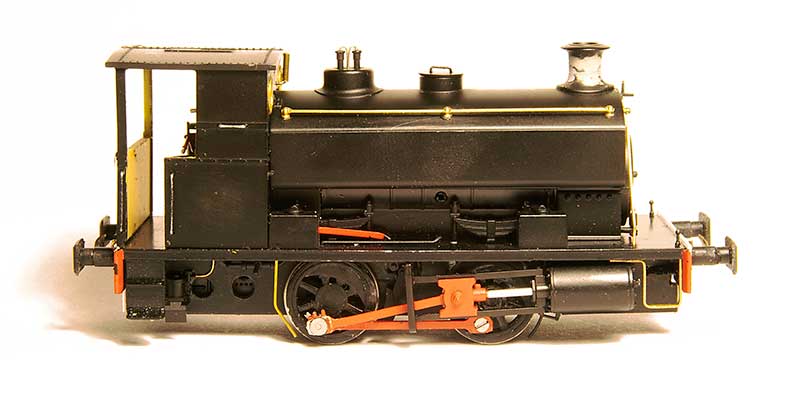 As can be seen in the previous picture there’s quite a noticeable gap between the chassis and the wheels. Of the limited detail on the chassis a lot of it pugs in as separate bits so its a relatively easy job to make some new overlays from 60thou plasticard and plug the bits back in.
 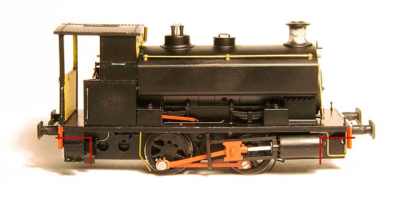 One thing I would advise though is to cut away the original chassis at the points shown (where the NEM coupling pocket is) as you will end up with very chunky and visible frames at the ends of the loco. Might be better to do 20 thou overlays and space them out so they are nice and thin. The arrangement of the brake shoes on the EoD locos seems the opposite way round to the way Hattons had modelled them with the shoes in front of the wheels not behind them and the linkages not visible at all. so these were rearranged. You can see the front crank pin screw in this picture. I also changed the front step to match prototype photos.
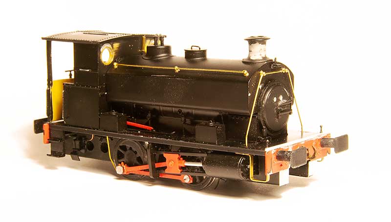
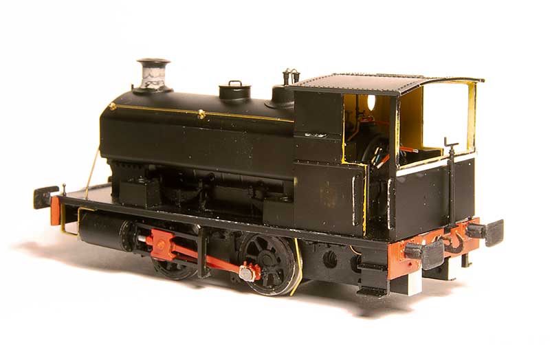 The rear of the cab. EoD locos had 2 types of cab, an enclosed one with 3 windows and this open version. The enclosed one is available from Planet industrials as a detailing kit. Given the layout is set in the rain my mini driver and fireman must be cussing me for not going for that one! My first thought was to scratchbuild a new rear cab from brass for strength but I decided to cut away the RTR one first to see if that would work instead, as can be seen it did. The handbrake is the supplied RTR one


