Pre-show tweaks.
Been doing some final pre show tweaks before Brettell Road heads off to York in a little over a week. 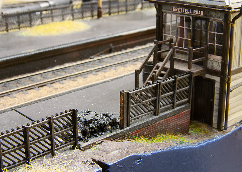
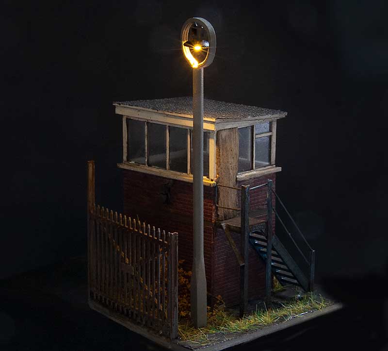
After the last show (nearly a year ago now) there was a little bit of damage picked up. Nothing too major and the kind of job that I intend to get around to at some point but then don’t. Case in point this but of fence which got squished. 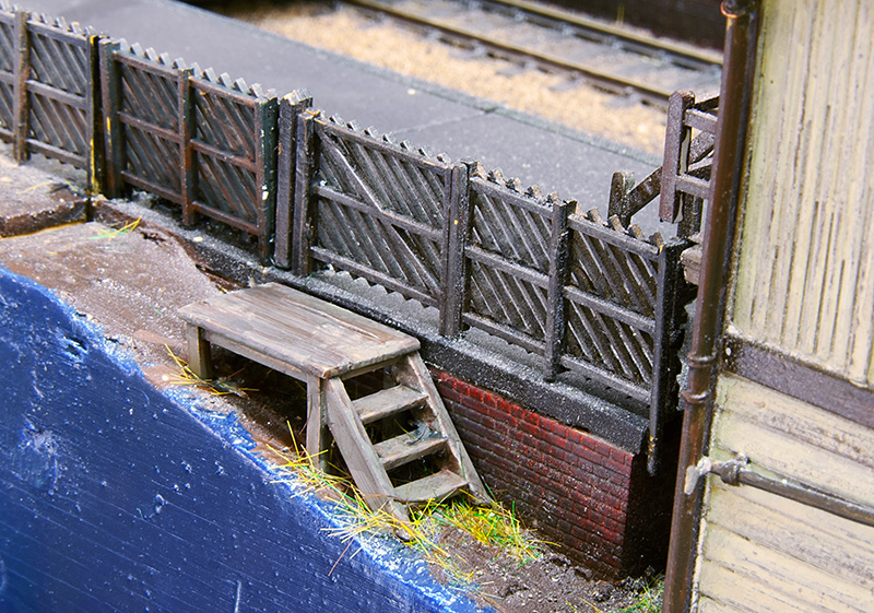 While working on this area I took the opportunity to add some rudimentary steps to the signal box. Something I meant to do at the start but didn’t. I had put the gate in but the poor signaller would break his leg falling off the edge of the platform! There was also a platform light that got bent and thats been repaired and replanted.
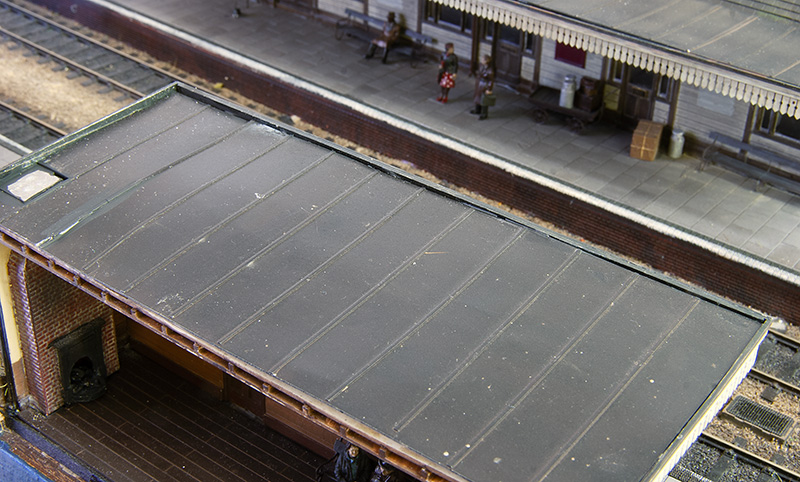 Something else that got bashed but didn’t actually break is the chimney on the platform shelter. This has very little clearance to the other board when packed up so rather than wait for it to get smushed I decided to make it removable. A few magnets popped into holes and a bit of steel on the roof and hopefully thats a problem averted. I also decided that the roof was a bit too vanilla for a building due to be closed in a week so I’ve had a look at this area too.
 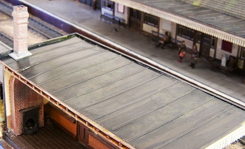 You may remember i talked about distress paint before when I was building the signal box and I’ve used it again here. For some reason it didn’t really crinkle up this time so a wash of Tamiya extra thin cement was painted on to add some more wear and tear. The mossy deposits are AK Interactive dark and light slime with some of their moss deposits.
Next is track cleaning and hoovering before packing the boards away, then the joy that is cleaning wheels!
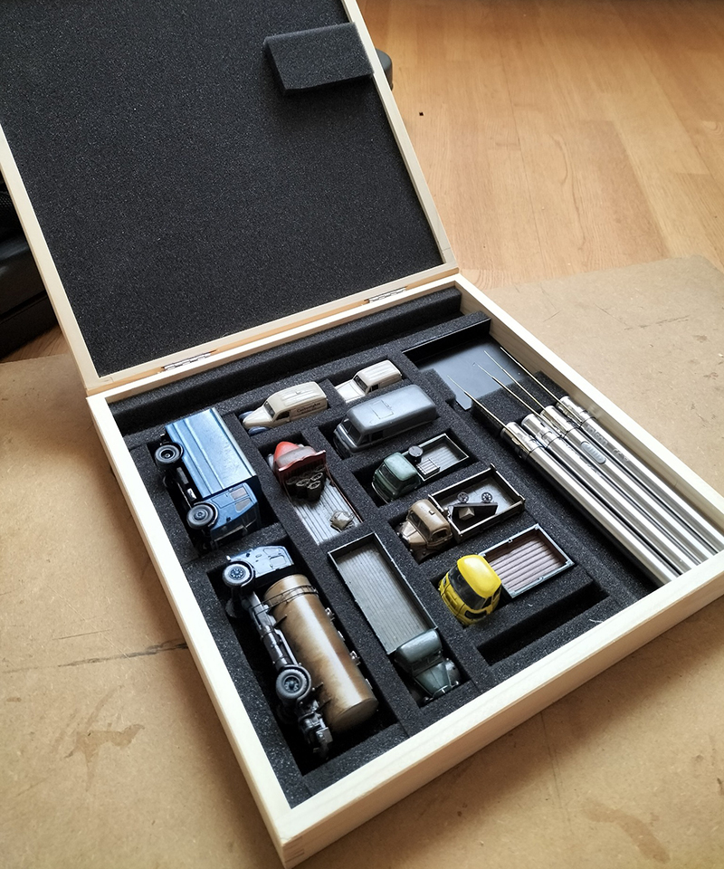 In an uncharacteristic fit of tidiness I’ve made a proper box for the road vehicles, removable chimneys and coupling poles. When I say ‘made’ I mean got a box off ebay for around a tenner and stuck some foam in it!
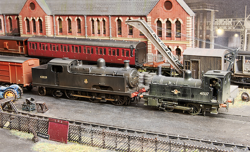
The saddle mounted tank I featured last time is done and tested.  Finally Railcar W14 waits for the road. The cats are undisturbed by its presence.
Info on the York show. Please say hi if you are going.
A trio of tanks.
A trio of tanks this time starting with…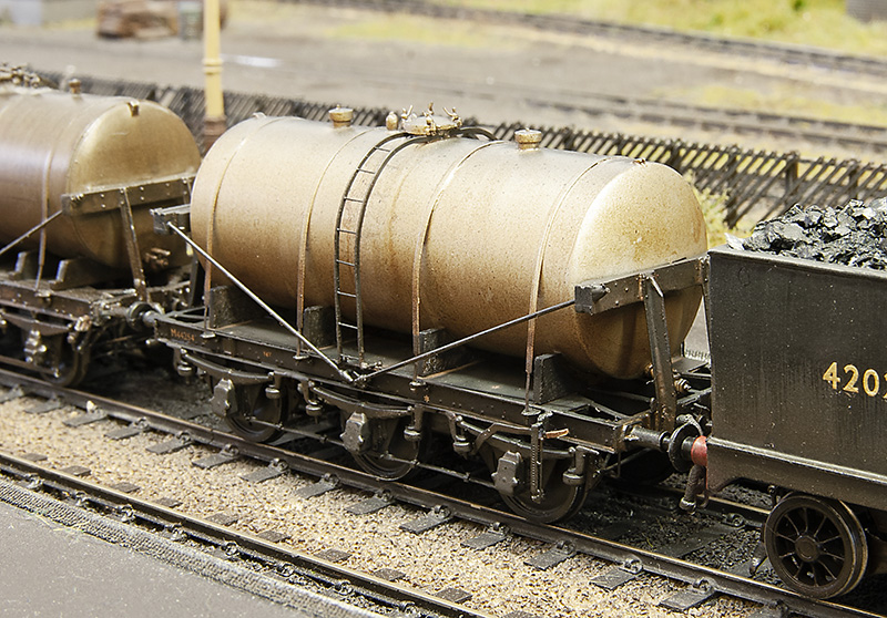 … the LMS milk tank I featured last time. Now ready for service.
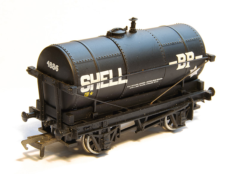
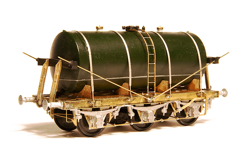
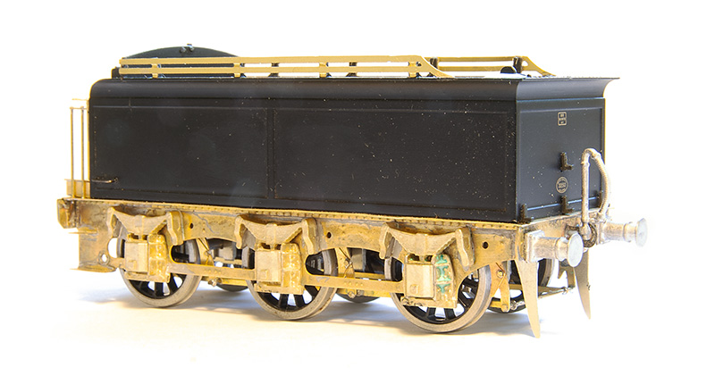
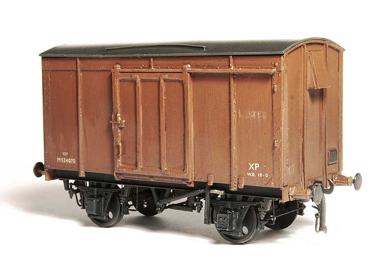
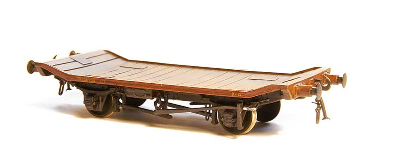
The Bachmann 14t cradle mounted tank wagon. Very much of its time with a very generic (and pretty rubbish if I’m honest) chassis. 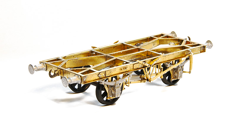
Luckily Justin does something a little more refined and very nice to build it is too.
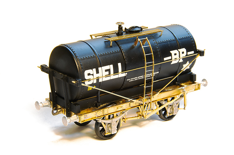
Ready for the brass bits to be painted. The ladder is only loosely in place. The walkway is from my box of useful stuff (I think Stenson models) and the buffers are from Lanarkshire Models.
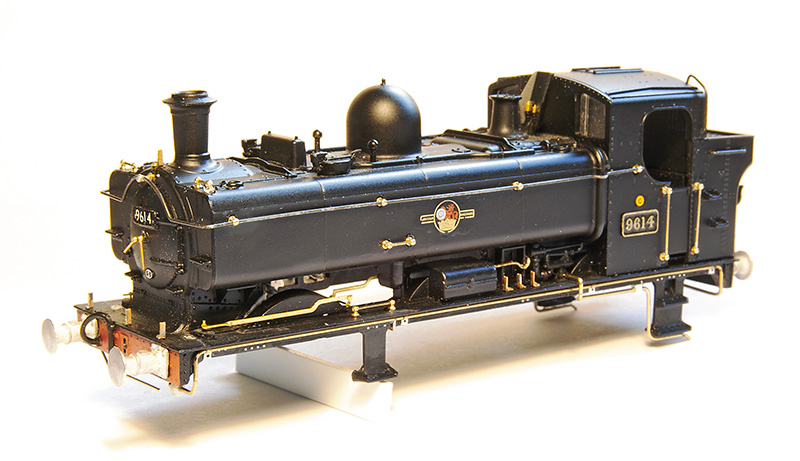
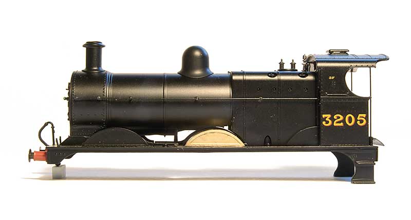
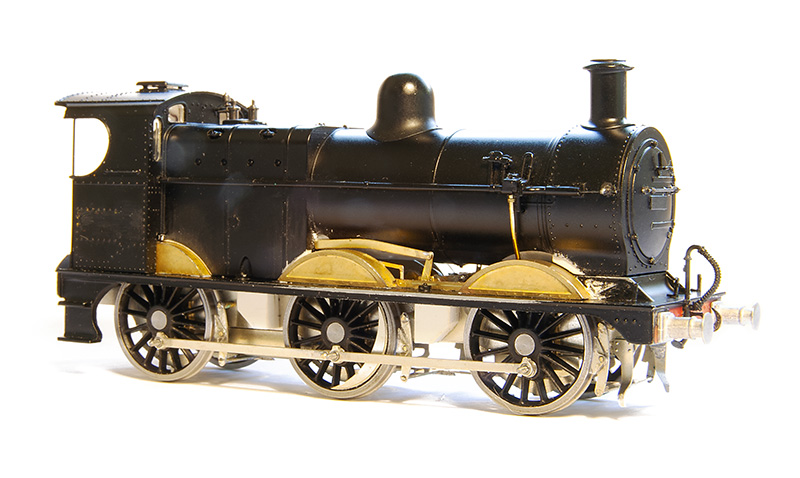
Still sticking with the theme of tanks but is a slightly dubious way, work in progress on a 96xx tank. I originally picked this up quite cheaply with and idea to include it in my scrap train. Round Oak scrapped quite a few locos, but it didn’t take me long to decide to do it as a working loco instead. Especially as a picture of this very loco heading a freight train through Brettell Lane cropped up in my facebook feed.
As far as I can tell this model by Bachmann is an evolution of the Mainline model I’ve already used to do my 57xx tank, with a later cab and other refinements. All of the handrails are separately fitted but I felt the handrail knobs were way too big so I replaced them with Alan Gibson ones. I reused the long handrail but as its not so wide i had to cut it in half to lose a little from the middle. The sandbox fillers are too far forward as they were repositioned with RT Models linkages but not before the front splasher was cut down in height. A compromise for the over sized flanges on the RTR wheels and something that has entered my ‘now I’ve seen it, i cant unsee it’ mindset when looking at model steam locos. Smoke box dart is also Gibson and the lamp irons are from Masokits. I also replaced the pipes on the footplate. Some 96xx had a bracket half way along with i quite liked but unfortunately 9614 was one that didn’t.
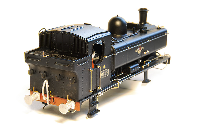 Rear view. The lamp irons were too high up on the bunker. This is correct for a 57xx but on the 96xx tanks they were lower. I was replacing them anyway. Buffers are Lanarkshire models. I prefer a better detailed solid buffer over a less detailed sprung one.
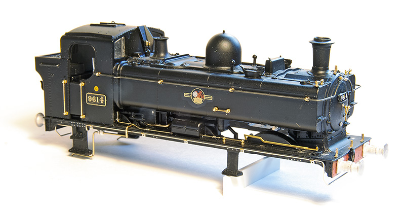
Drivers side. The pipework just in front of the cab is the same on both sides of the model. Again OK for a 57xx but on the 96xx they were different with a somewhat more barren look on this side. The footplate pipework is also routed differently around the cab footsteps. Chassis will be a high level one with my working inside motion bodge as described here. https://p4newstreet.com/an-unremarkable-little-tank-engine-part-1/
 Finally something that you will never see – Brettell road in the sun! It was coming in the shed door and caught my attention.
return to milk tanks
My history with milk tanks has been, to an extent unnecessarily convoluted. Originally I planned to build a David Geen kit for a midland one and I got the Rumney Models underframe for it in preparation. However when I came to get the kit from David he only had one left and that was for a GWR one. Justin kindly swapped the chassis kit for me and, as I’ve mentioned before, doing battle with my collection of bits I ended up with my model of a milk tank.
However the desire for at least one LMS one never went away and for more years than it really should have been I would discuss the idea of doing one using Rumney bits with a Lima tank when I saw Justin at a show. Apparently I wasn’t the only one
Well finally, heres what I’ve come up with, The only bits of the Lima one left are the tank – end supports and filler hatch. The rest is pretty much all Justin with buffers from Lanarkshire models and the tank supports kindly cut for me by Tim Horn.
The diagonal bracing is obviously over-length at the moment. The strapping isn’t tight and the ladder is just rested in position until after painting. This seemed much less of a fight than my other one, so much so that I’ve ordered bits to do another 2.
Duchess progress March 2025
Some progress to report on the Duchess test build.
The original design that Geoff did for the cylinders was the same as the 7mm scale Finney kit. That uses cast slide bars soldered to the rear edge of the cylinder frame. In 4mm scale that wasn’t going to work so David has redesigned this area to use a layered etch that goes through the rear face and solders to the front. This will be much stronger.
 The cylinders viewed from above with the wrappers in place. Just behind the cylinders are the Valve rocking arms which as they need to be removable are held in place with a small screw.
Theres a lot of piping on the footplate of a Duchess! 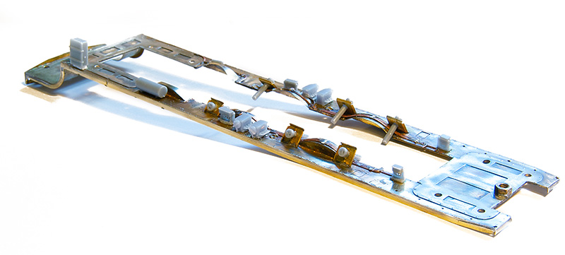
The footplate is pretty much complete now.
Made a start on the valve gear
Progress so far.
A batch of good old Airfix kits
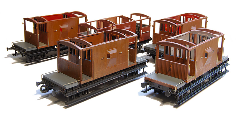
I recently picked up a batch of good old Airfix wagon kits. There were 4 brake vans, a 35t tank, a 16t mineral wagon and a cattle van. Of those one of the brake vans was finished and another one along with the 16t mineral were semi completed. I really wanted the brake vans as I had identified a need for more BR ones and more that were fitted as up until now I didn’t have any at all, just a couple of piped ones.
 Note to self – if you’re going to batch build some wagons don’t pick ones that have loads of different sized handrails!
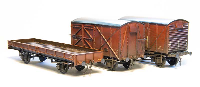
 The first 2. A piped one and a fitted one, both built with Bill Bedford W irons, Rumney models springs and axleboxes and additional details.
 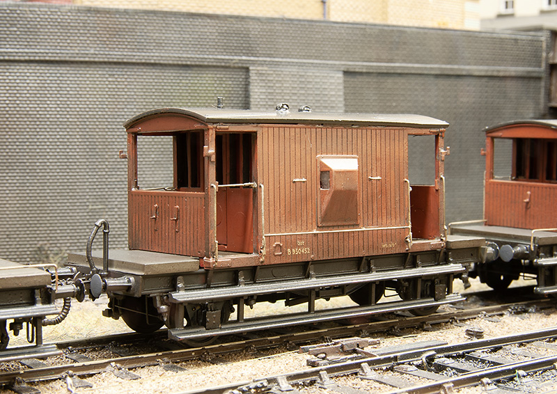 This one is a BR build of the LNER design note the shorter steps, no end handrails and different lamp irons. Build was the same as the first 2.
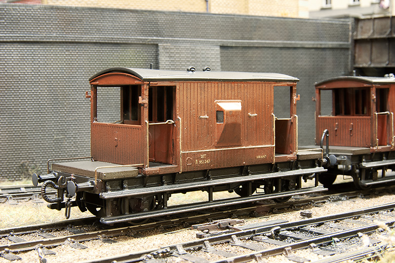
This was the last one and the one that was already built. I replaced the handrails and roof and added the same details as the other 3. This one is unsprung.
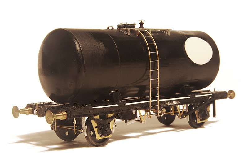
On to the tank wagon. Not one this done before. This is sprung with Bill Bedford W irons. As supplied the solebars are too shallow so I carefully cut the top rib off flush with the face and added a new top rib from microstrip. Buffers are from my draw of buffers and I think they may be from A1 models. RT models do a nice little etch for these and while the ladder supplied is really nicely done it is a flat etch so I replaced them with ones from Rumney models. I replaced the brake gear with bits from the spares box.
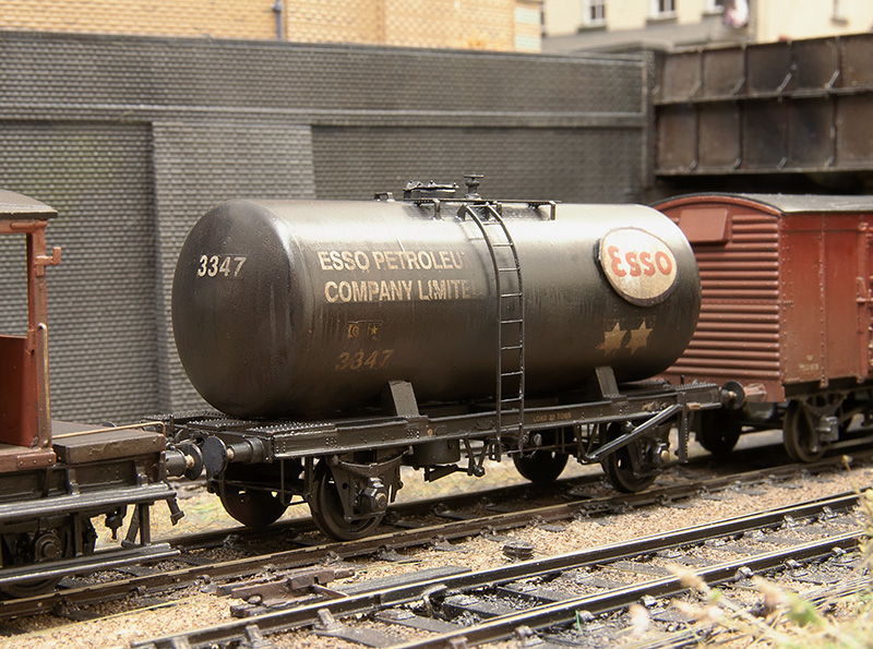
The finished wagon. Transfers are from Cambridge Custom Transfers.
Flights of Fancy – Part 2
 I ended the first part of this project by mentioning I needed some bits from Scaleforum. One of these was the injector which I modified a little from an Alan Gibson one.
 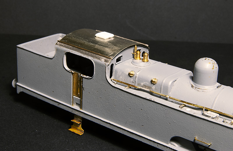 I also needed some firebox wash out plugs. Again Alan Gibson did the honours. It’s worth noting that they are not on the same places either side. The cab roof was just a bit of nickel silver rolled to the right radius and a few bits of strip for the rainstrips. The vent was filed up from Evergreen section. While on the subject of the cab the kit includes some bits and an etched floor. I found the handbrake column, if mounted to the cab floor as the kit was designed, gets in the way when trying to mate the body and chassis together so I cut it from the floor and mounted it to the body instead. The kit specifies that the reversing screw is mounted on the left side of the cab but, while hard to see in photos, it seems to be mounted to the right side so thats what I did.
 With everything in place and being happy wit the fit of things the body was given another light undercoat before the missing rivets were added from my dwindling supply of Archers along with some from Railtec. Thankfully the flatirons dot have a lot of visible rivets.
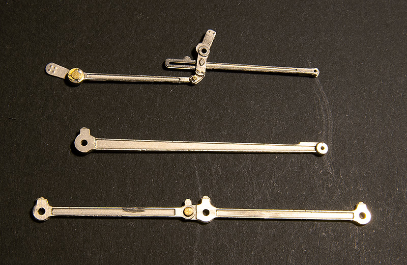
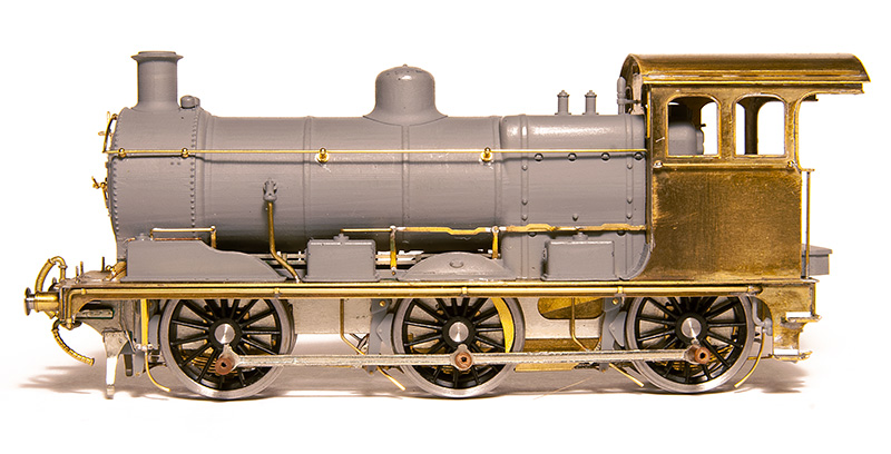
 I don’t normally take a painted but pre-weathered picture but this time I made an exception. I mentioned in the last post that because of the carzatti front axle the coupling rods seemed backwards to the norm with the joint ahead of the middle axle not behind it. When No.2000 was modified this remained the case. The kit has the coupling rods the normal way round with the joint behind the middle axle and I’ve never seen a model flatiron (in either 4mm scale of 7mm scale) that addresses this. I found 52f models do a set that have the right wheelbase with the joint in the right place so I used those instead. One little tip that seems really obvious but I’ve never seen anyone mention (perhaps its because it is obvious to everyone else?) is that I line up the coupling rod on this side with the orientation of the grub screw on the final drive gear. It makes accessing the grub screw simple should you need to in the future as you know where to stop the wheels rotation.
Below some pictures of the finished loco with my usual caveat of still needing coal and a crew. 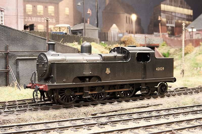
 With her baby sister!
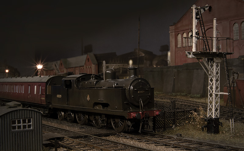
Flights of Fancy – Part 1

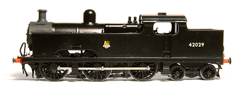
Long time readers may remember this illustration I did a fair few years ago. At the time I was toying with the idea of BR Flatiron for Brettell Road. People who know anything about these locos will know that they only made it as far as 1938 before the lastof them went for scrap but my theory was what if they didn’t and made it another 2o years or so? After all we are all happy to bend the historical truth when it comes to places but why not locos too?
A brief history
Samuel Johnson of the Midland Railway had identified a need for a large passenger tank engine in 1903 and while a 0-6-4 seemed a logical progression of their 0-4-4 tanks several ideas and arrangements were put forward both before and after the design by Deeley was settled on. These ranged from a 4-4-4, a 2-6-2 with odd split side tanks, through several variations of outside cylindered 2-6-4’s and a 4-6-4. All of the class of 40 were built in 1907. As it turned out this was not a wheel arrangement that would become at all common in the UK. The front axle was mounted into a Carzatti slide giving extra play and resulting in a somewhat backwards arrangement of coupling rod with the knuckle joint ahead of the middle axle and not behind it as was the norm.
In early LMS days the class were fitted wit new superheated Belpair boilers resulting in a different firebox and being longer, the boiler now sticking out from the front of the tanks. The cab spectacle plates were also changed at the same time.
In 1928 loco No.2015 derailed at speed near Newark and a passenger on its train was killed. 2 more derailments occurred in early 1935. The first instance was when N0.2023 derailed at Ashton under Hill in February, killing its driver. 3 weeks later number 2011 was observed by railway inspectors operating between Leicester and Burton upon Trent only to itself derail 5 days later at Moira. Fortunately this time no serious injuries occurred. But the reputation had set in, the class were well known as rough riders on anything other than perfect track and were noted to run smoother going backwards.
An idea not completely without precedent.
The case for these locos lasting longer than they did is not without precedent. Class leader N0.2000 underwent some modifications to see if the riding could be improved. These were the replacement of the front axle arrangement with traditional springs (giving a different look) and an improved bogie with side bolsters. No 2000 was tested against an unmodified classmate No.2012 which itself had recent general repairs and not yet clocked up 1000 miles since. Both locos were considered to be in first class running order.
On the first test No.2000 ran between 35 and 50 mph before selling back to 35 and it was reported that the engine rode very steadily with no side movement reported of the trailing bogie. Test 2 saw No.2000 run between 45 and 50mph settling back to 45 with the same results. Test 3 was run at 55 and occasionally 60mph and this test was satisfactory enough to try test 4 where she was run over 60mph, reaching a speed of 67 before selling back to 65. It was reported that a slight amount of side oscillation developed and a slight roll but was still considered satisfactory riding.
No.2012 ran 3 tests. Test 1, 35mph occasionally touching 40 and the riding was reported as good with a slight oscillation and roll being perceptible on the footplate. Test 2 saw 45mph with occasional 47 and the riding was considered fairly good but with more oscillation and tendency to roll. The final test saw running at 55mph with occasional 60 and the riding was reported as rough with the oscillation and roll said to be pronounced and the front end having a tendency to develop an up and down surging motion.
Although the results of the modifications to No.2000 were good Stanier decided that the rest of the class were not worth altering and between 1935 and 1938 they were all scrapped with many of the (standard) parts going on to other locos. It was reported that many of the boilers were used on 4f’s.
But what if Sanier thought the modification were worth doing to the entire class? They were only 30 years old and many midland locos lasted much longer than that. As the boilers went to other locos they were obviously good so it it such a leap to think that a modified flatiron could indeed make it into BR days with only a slight tweak of history is it?
The Model
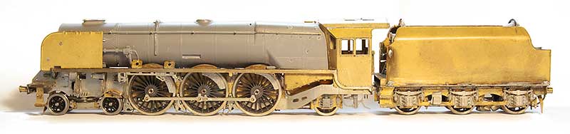
Luckily for us South Eastern Finecast do a kit for these loco’s and I’ve had one in the stash pretty much since I did the drawing above.
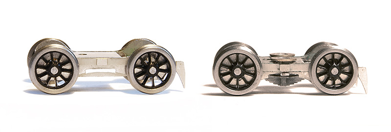
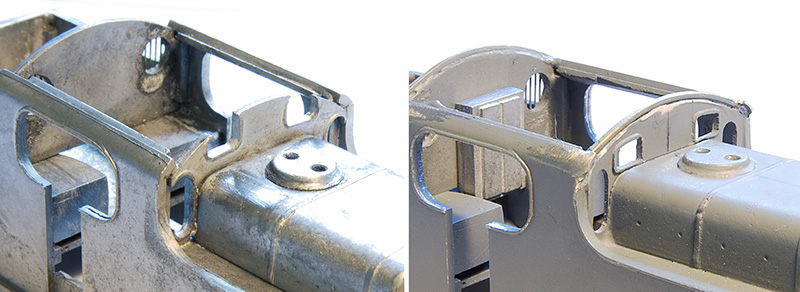
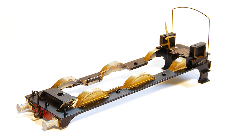
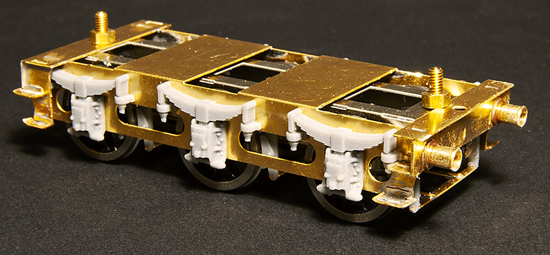
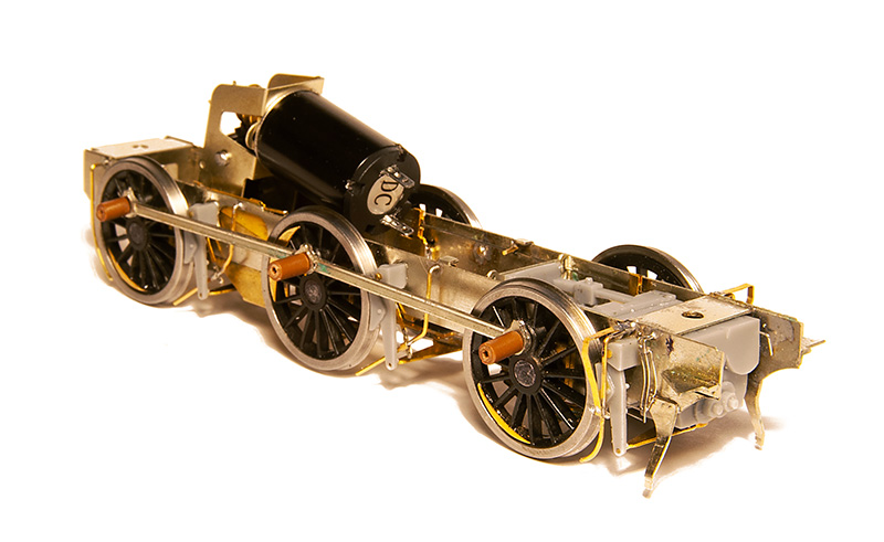
Starting with the bogie as supplied on the left and my modified version on the right. It’s been modified mechanically to provide basic springing on all 4 wheels and a basic form of sprung side control. As supplied the bogie is designed to be attached to a swinging arm much like the RTR guys tend to do. I didn’t really like that idea much if I’m honest.
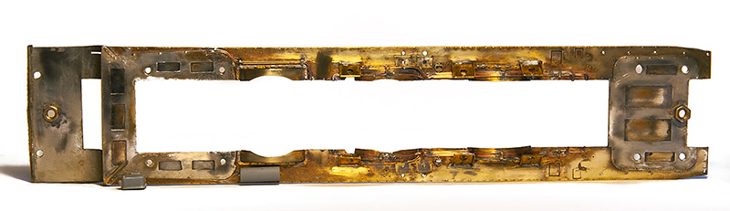
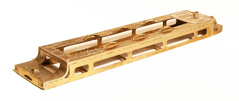
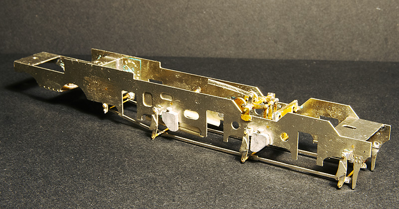 The main frames modified with some spare Brassmasters inside motion bits. I considered there was no way you would be able to see working inside motion so just modelled the bits I felt you might see if you looked hard enough!
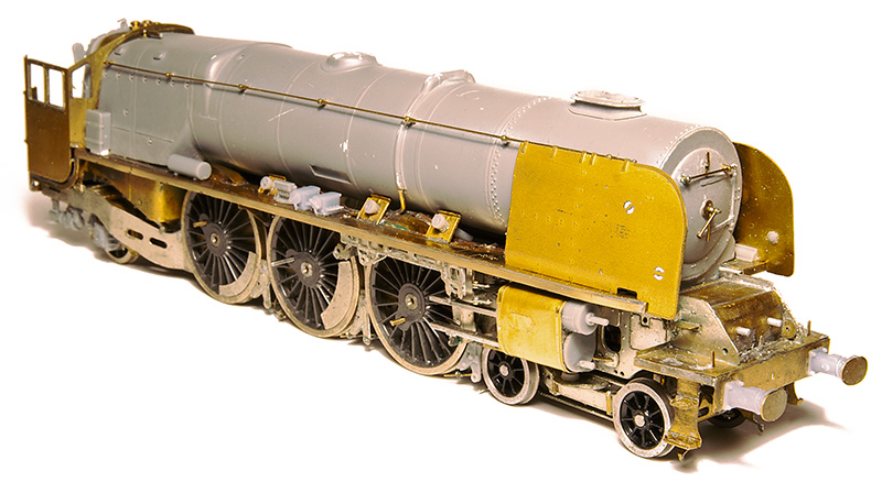
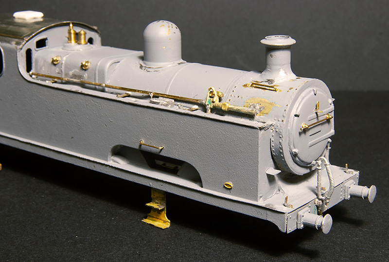
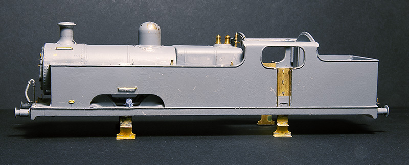
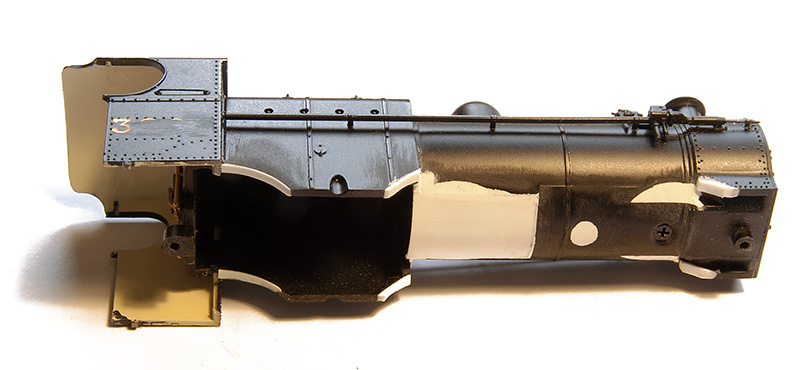
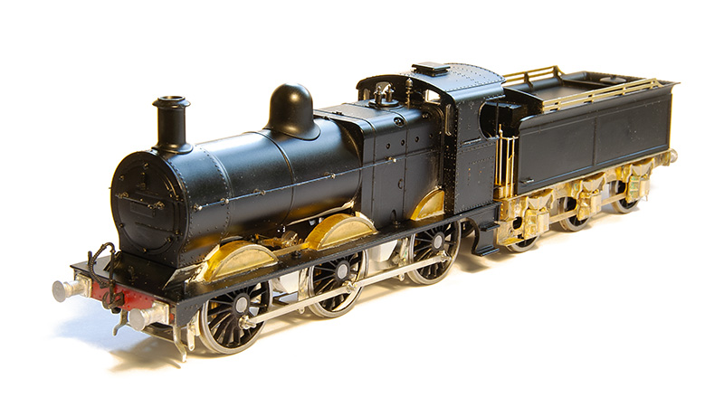
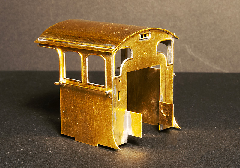
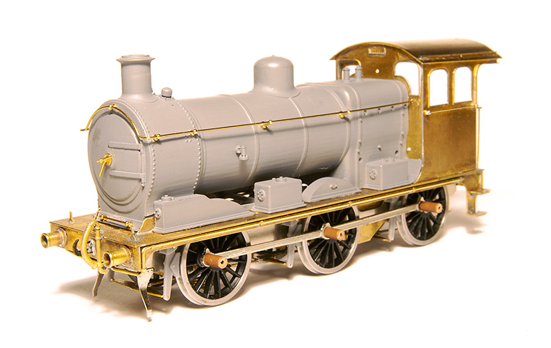
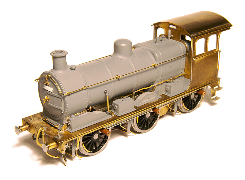
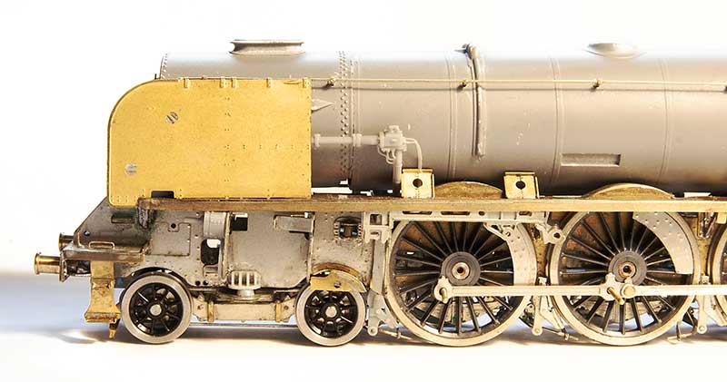
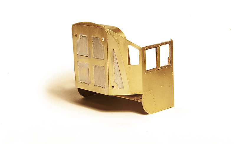
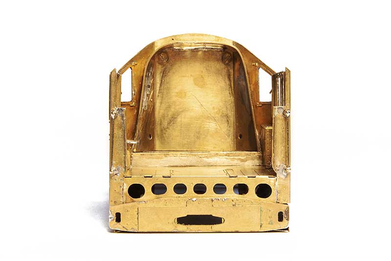
The cab Spectacle plate is a particularity weak point of the kit as it bears only a passing resemblance to the real thing, I made a new one from plasticard as can be seen on the right. If anyone wants the drawing for this (which I admit is a best guess on my part) it can be downloaded from here. The rebuilt cabs also seemed to have slightly longer roofs than the originals and little bits of Nickel strip were soldered to the corners to replicate this. 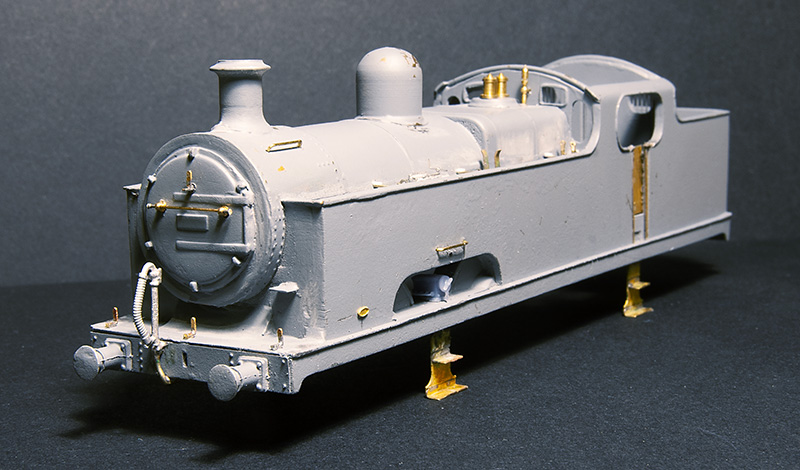 Front view. The kit relied on an upper half of the boiler/smokebox merging with the lower half which is cast as part of the tank front and this forming the front of the smokebox. The end result wasn’t all that round so I cut it back and used a 22mm copper ring in its place Buffers are from Lanarkshire Models and lamp irons from Stenson Models
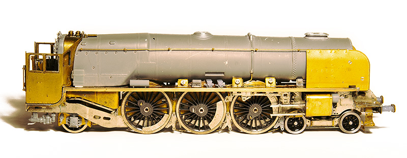
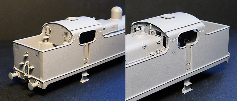
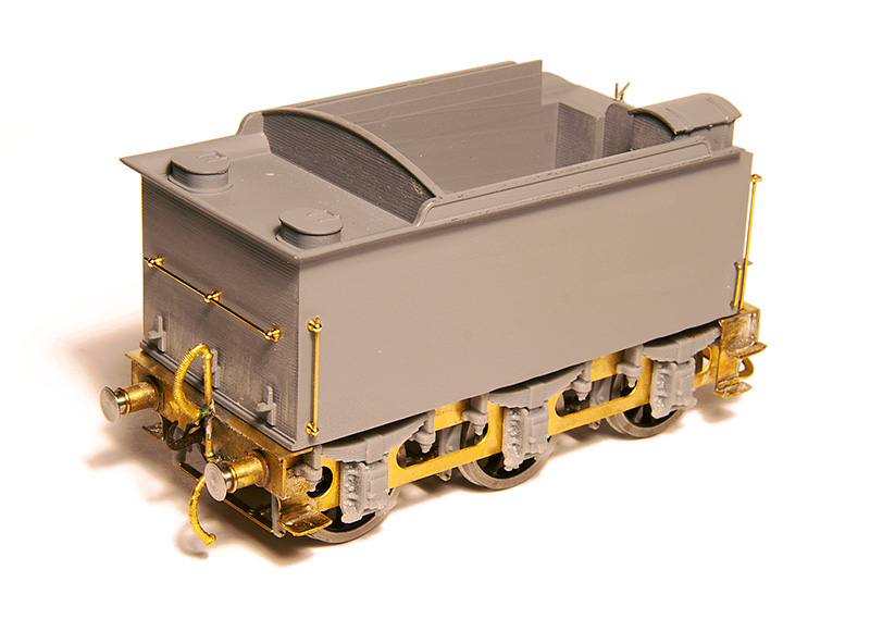
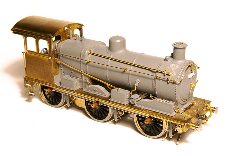
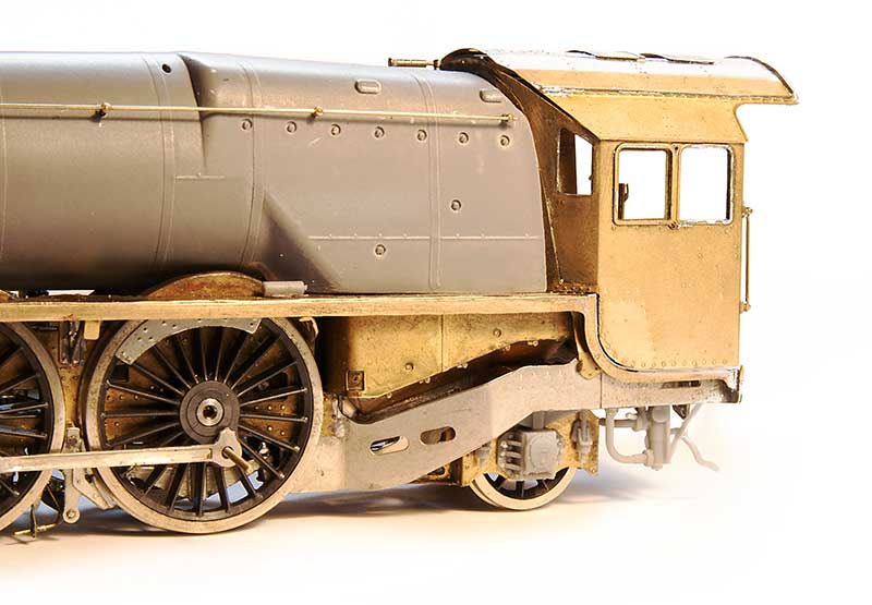
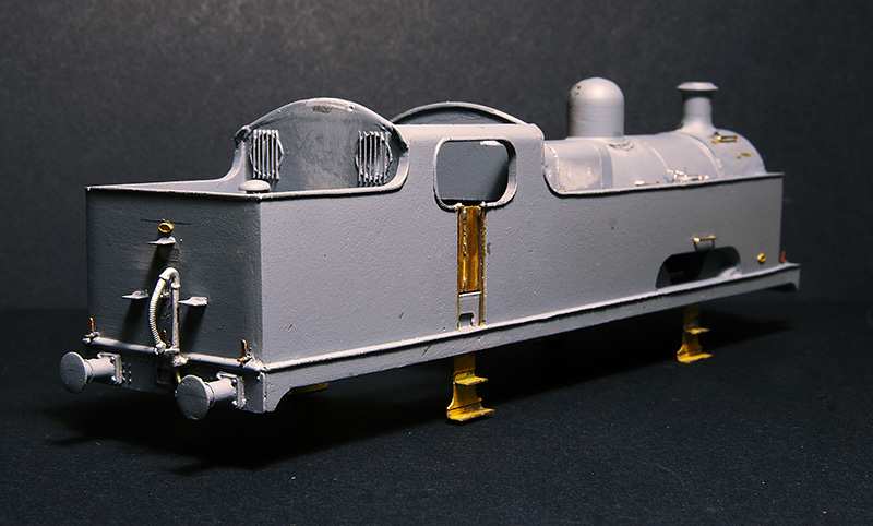 The rear view. The steps are cast into the rear of the bunker and where a little chunky. Also the top one was too low so these were replaced with some of my mk1 coach end steps. The window frames are from a Mainly Trains spectacle plate etch. Note the larger buffers on this end.
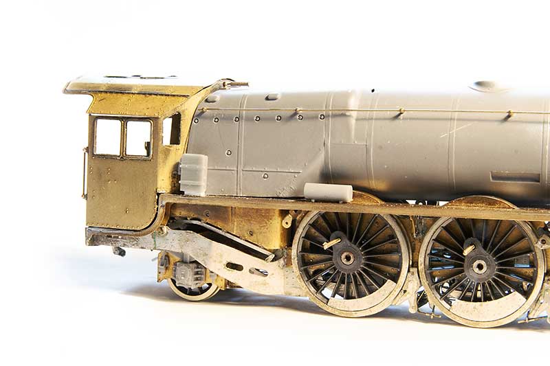
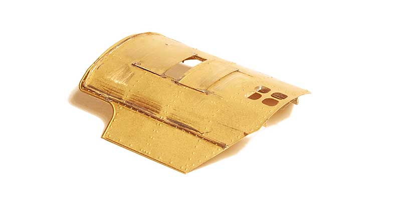
 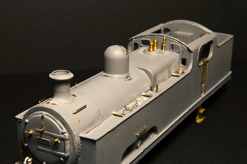 The top of the tanks are vague as supplied with just casting for the water filer caps and 2 air vents that were related to the water pick up gear. In reality only 2015 had this fitted so they should be left off all other models of the class. This is my educated guess of what should be there but i do think there should be more clutter than this. Photos of this area are rare and so far I’ve only found 2
Progress will now need to wait until after Scaleforum where i need some more bits.
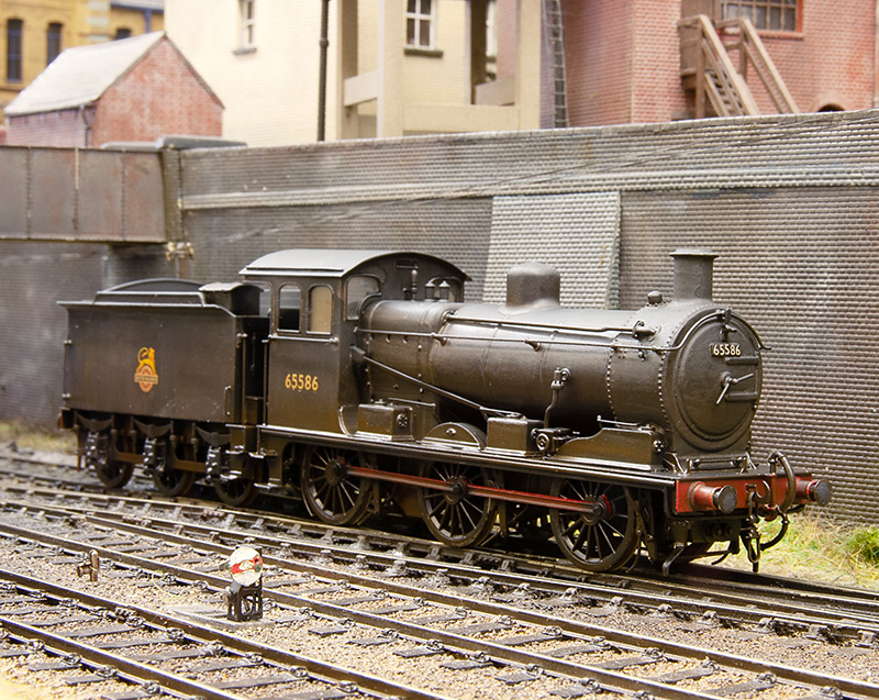
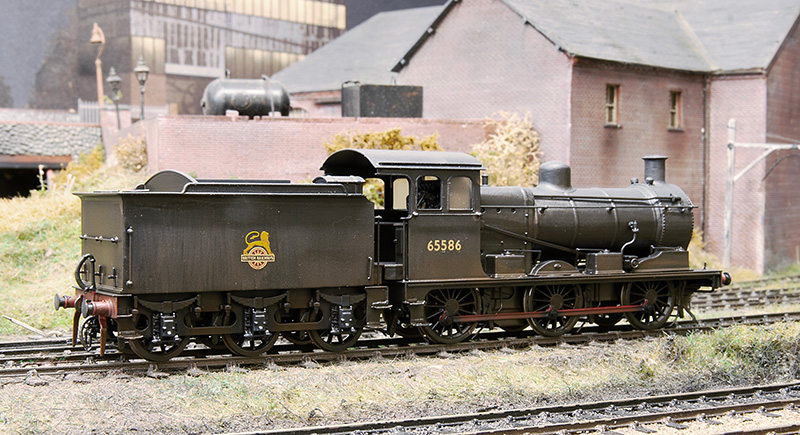
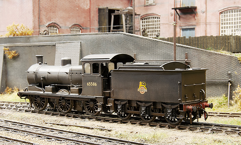
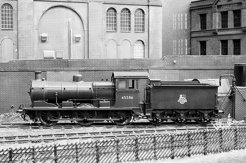
Its all gone a bit Eastern Region – Part 2
Earlier in the year I showed progress on a test build of the Brassmasters J17 kit test build. What follows is progress since then.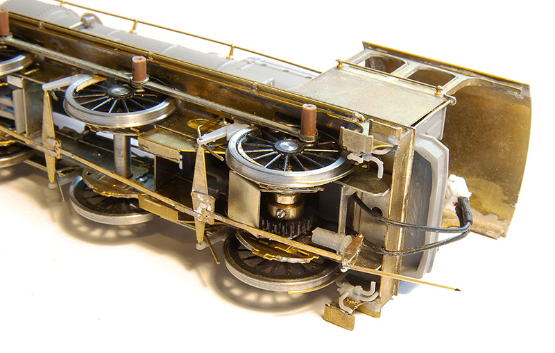
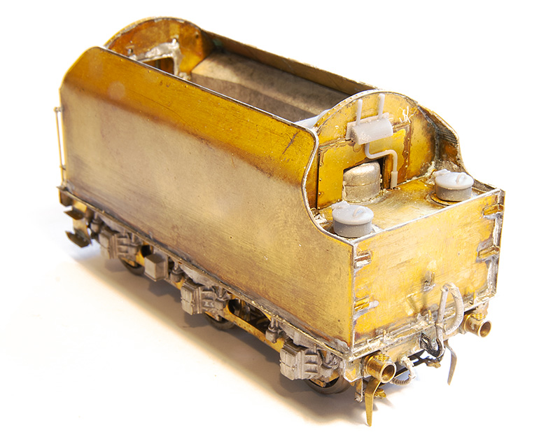
To be fair there wasn’t a huge amount left to do as I left it. One of the jobs was the business end of the brake gear on both the loco and tender. 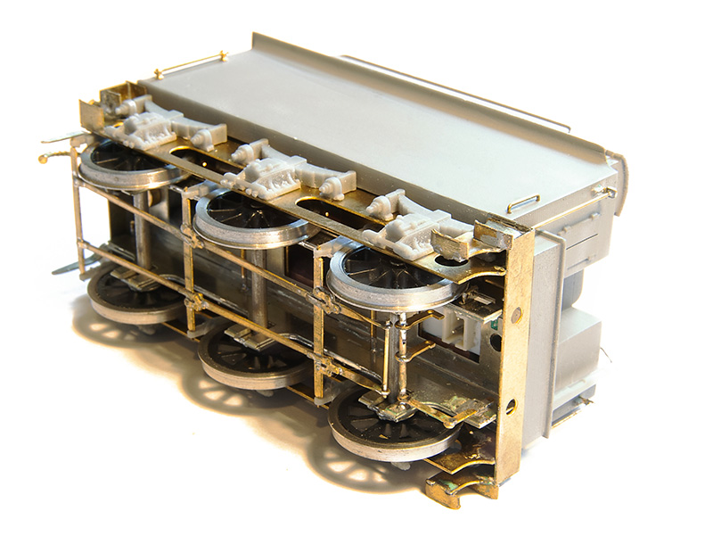
 The other little job on the tender was the guard irons which had been missed off the test etch. These were fashioned up from scrap using a scaled image of the production etch as a guide.
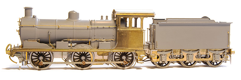
When I showed the side on view before I had managed to get the sanding linkages all wrong. This was subsequently corrected.
(Video © Tim Horn and used with permission) Then it was off to Tim’s for a few days work blocking in the basic greenery on North Elmham which was also an ideal opportunity to give the J17 a chance to stretch its legs. It was unweighted at this point except for a few pound coins in the tender. Attention then switched to getting Brettell Road ready for Scalefour Crewe and besides I thought it would be good for the loco to be displayed on the Brassmasters stand in the raw so to speak. However since then it’s now been finished off with the exception of a crew and some coal in the tender.
For part one of this little project click here
Time for an Update
Its been 10 months since I did an update on the Duchess test build so its probably a little overdue.
The first bit of news, for those who don’t follow the Brassmasters blog is that Geoff Hurley, the original kit designer, sadly passed away at the end of November 2023. He had been with Brassmasters for 20 years and in that time he designed their kits for the rebuilt Royal Scot, the LMS 4F and the Princess Royal as well their detailing kits for LMS locomotives. The Duchess was his last project before he became ill in 2022. I had a hope that I would get it finished and he would be able to see it but alas that wasn’t to be.
This had meant that at lot of head scratching and trying to figure out where the project was has gone on since (not much of it by me I must add). So theres actually been an awful lot of work going on but it may not look like it.
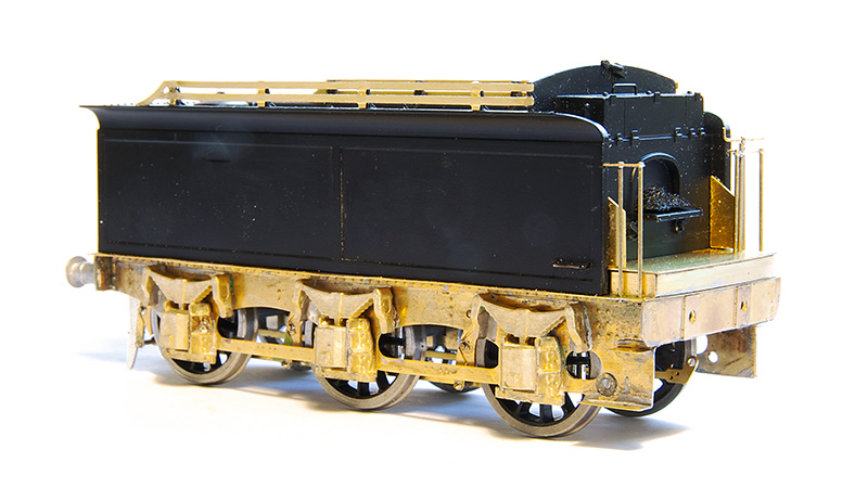
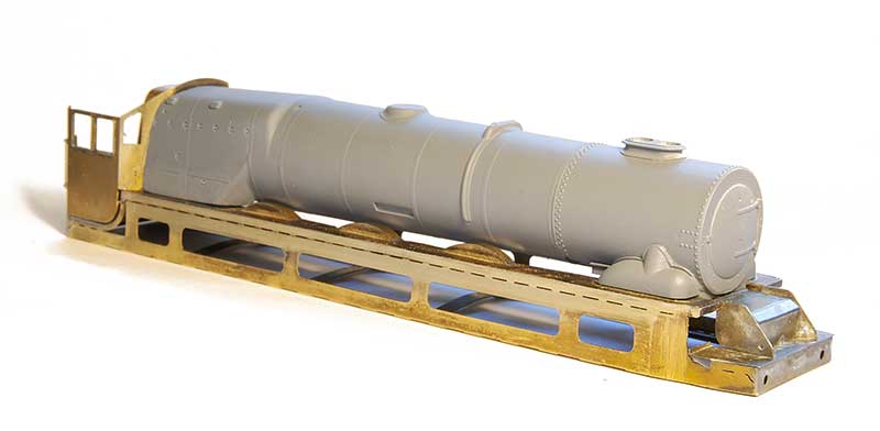
Some new bits for the tender. Originally the water tank hatches were white metal castings but these have been changed to 3d prints produced by David. The external part of the coal pusher is another 3d print.
Moving foward the exhauster pipe and the under cab injectors. The latter have been through several versions mainly because of how we were going to mount them to the loco. This latest version seems to have cracked it but has necessitated a slight change to the etched artwork. The cab roof is a loose fit.
 While on the subject of the cab heres some of the inner detail.
Some of the footplate details in place.
Moving on to the front, with health problems at Markits at the moment and being unable to supply stocks of their oval buffers we have looked at a 3d printed body with an etched head. This allows the buffer to be much more accurately detailed and while it does lose the springing the prototypes were not particularly know for coupling up to trains at this end.
3F and using a Brassmasters Easychas conventionally.
Ive always quite liked the Midland 3f tender locos. They seem to be quite nicely proportioned, more so than the 4F’s that looked kind of tall and somewhat top heavy. A while ago in quick succession I picked up a Bachmann body followed soon after by a tender body and a Brassmasters Easychas for it. In the last week or so Ive decided to get some sort of progress on it.
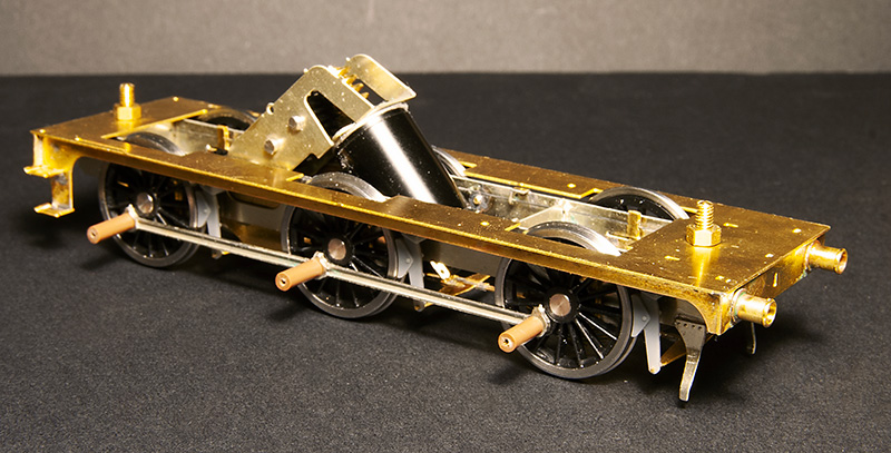
 So starting with the tender. I never had the Bachmann chassis and if its anything like most RTR tender chassis it will no doubt have all been a bit flat and kinda naff. Brassmasters do a detailing kit to replace the tender chassis completely so I used that. This is just built as per their instructions.
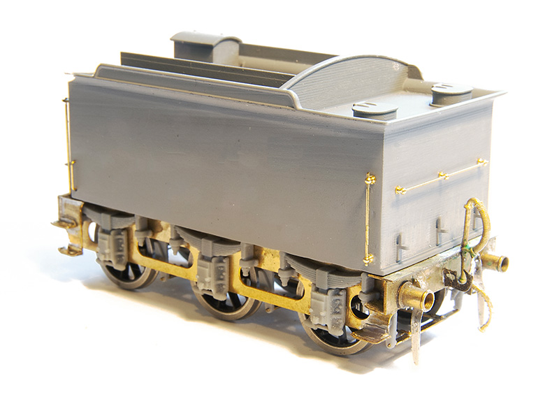
 The rear end. Buffers are from Lanarkshire models as is the vac pipe. I think I’ll replace the lamp irons too.
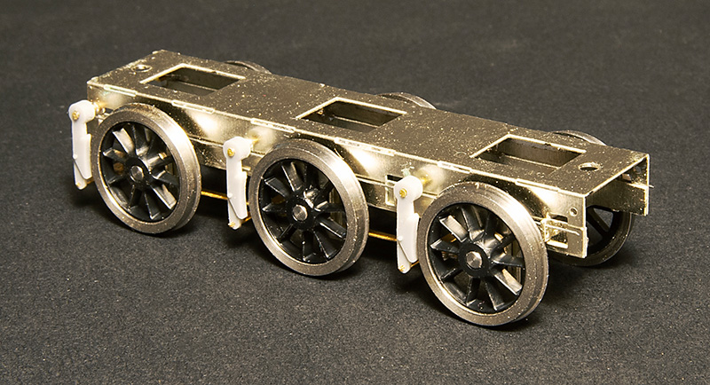
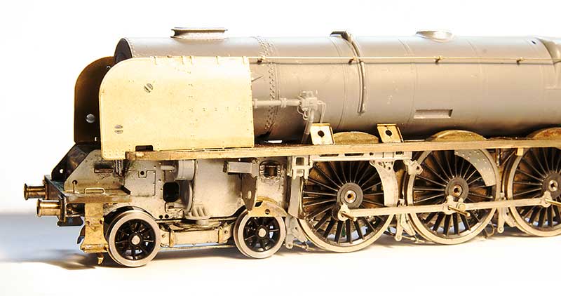
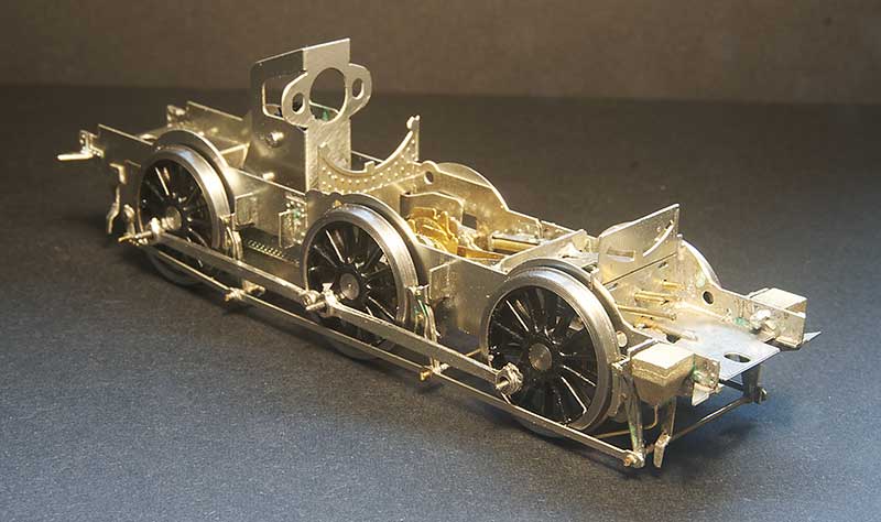
On to the loco. If I had the original chassis then based on the 1F I did I’m confident you could have something up and running in a somewhat leisurely afternoon. If you use the Bachmann coupling rods and brakes you might not even need to fire up the soldering iron! However as I didn’t have the Bachmann chassis I decided to build the chassis up as a more conventional one by adding spacers left over from a High Level Models Jinty chassis kit. As the easychas caters for EM and p4 the EM spacers are perfect. If you don’t have any leftover Jinty bits though Alan Gibson do a neat little etch of spacers.
 Before I show you the chassis though some decisions need to be made. The splashers suffer from the usual RTR problem of being too big. Brassmasters do a separate etch for ones that are the right size. The above image shows a comparison so you can decide if it bothers you or not.
 As you can probably guess it bothered me so they were all replaced. The original footplate has a solid floor back to the front of the chassis casting so I cut that out. The new reversing lever is part of the chassis kit and the boxes on the side of the cabs have been thinned down by 2mm as per the instructions.
 All this means that a little bit of rectification is needed on the body as it had recesses in the boiler for the original splashers that are no longer needed. I believe the Bachmann chassis block comes quite far forward so the base of the boiler was put back in using layers of thin plasticard. Theres not really much else to do to the body other than this.
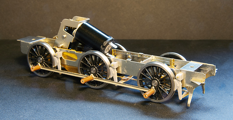
 Back to the chassis then – with the inside motion kit from the 4f – You didn’t expect me to leave a gaping hole did you? The gearbox is a high level loadhauler+
How the loco looks mocked up. I will leave the sandpipes until the very end as they will trap the centre wheels in place.
Going over old ground
Ive recently been doing a few revisions on the layout.
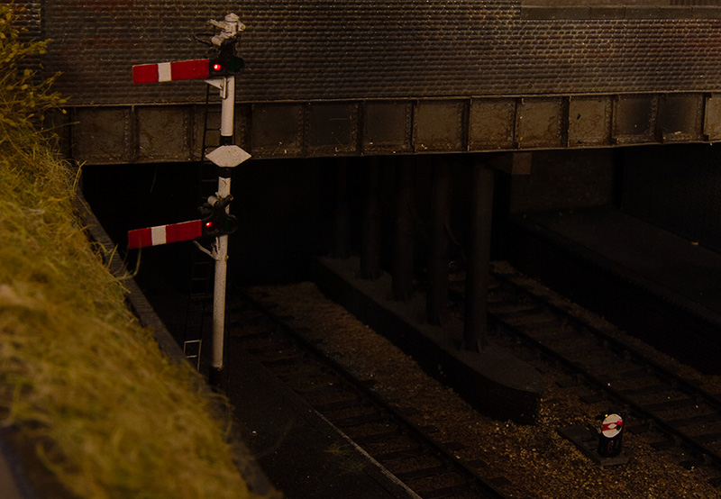
 The first was prompted by a failure. It had always irked me a little that the above lamp was a little bit crude and the top wasn’t really the distinctive shape the lights at Round Oak had. Being at the back in a dark corner it wasn’t noticeable enough to invest any time into. However when it recently failed why not kill two birds with one stone?
 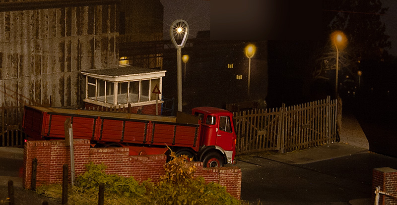 So after a bit of tweaking I’m much happier with it now.
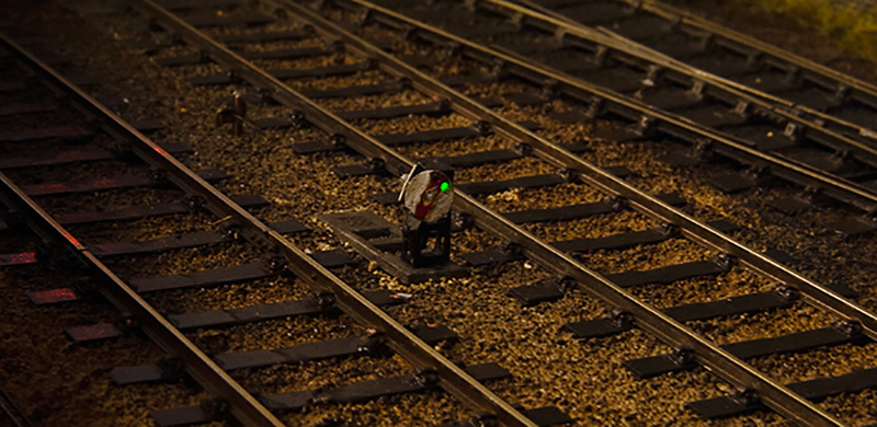
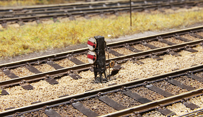 Ground Signals. I originally used the MSE kits but I had found a few drawbacks. First thing was A few had took some knocks while cleaning the track. As they use a whitemetal casting for the main body and legs they really didn’t like this at all and were starting to look a bit bent and battered. Secondly as I had fitted lights there wasn’t a lot of room to work and I had just drilled out the lamp housing and shoved a nano LED in there with slightly mixed results.
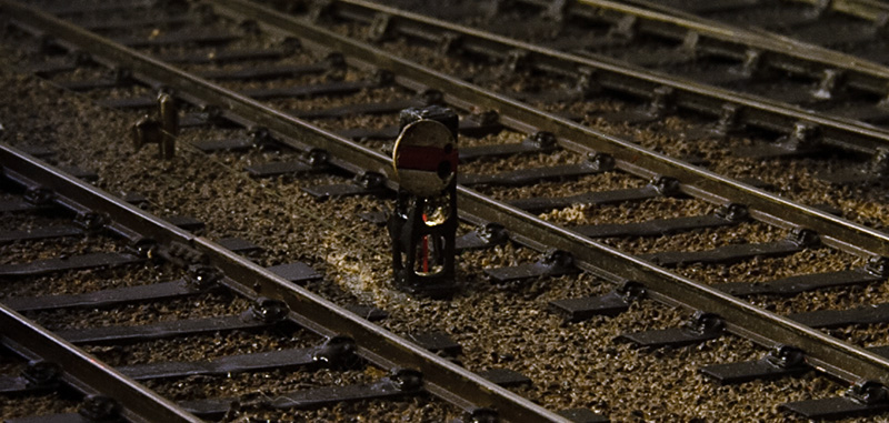 One consequence of this wass more light bled out of the bottom than through the signal despite various attempts to fill the hole
So step in the Palatine models etched kits as a replacement. These are hopefully stronger and being an etch theres more room to position the LED in a better controlled way. I say more room but in 4mm scale ground signals are tiny but because of that even a slight gain is a big help. I modified the kits a little to make them work and drilled a couple of holes for the lights. Results are below
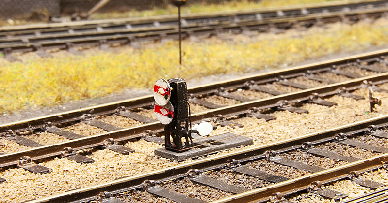
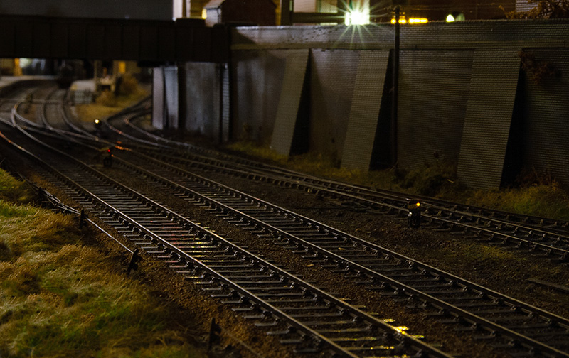
On the subject of signals Ive been playing around with resistors again to try to get the lamps a bit closer to how the real thing looked and less like a modern colour light. I think I’m there now.
Up on the road Ive added a few telegraph poles meaning I think I can call this area finished now. 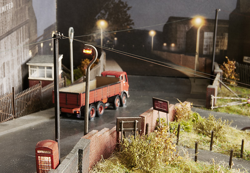
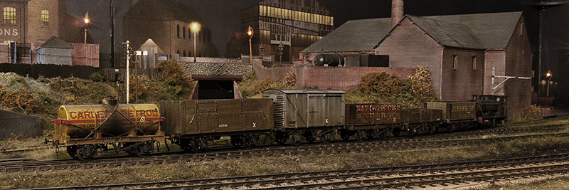
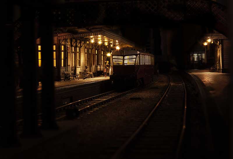
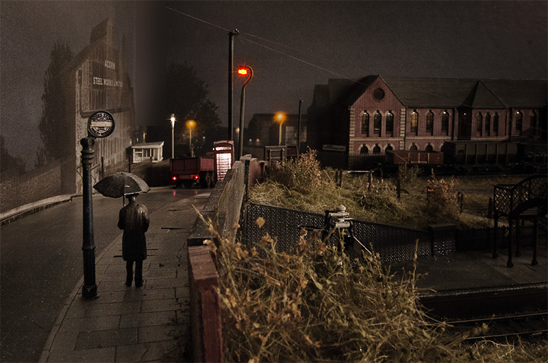 A revisit to my classic (or is that cliché?) scene. This time a wider verson.
Back to wagons – and a correction.
A while ago I did a batch of shock opens including an attempt at an ex-LMS diagram 1983 variant. Justin of Rumney Models noticed that I had used the same ends as the BR version with inset corrugations while the LMS wagon has corrugations that stick out. Something I had completely failed to notice myself. So that wagon had its top lip removed and renumbered back to a BR one. A new kit was brought (well a few actually – saves on postage!) and a second attempt made using cut down spare ends from a Parkside 12t van kit. The BR version is at the back. Theres a few other differences too like the bang plates for the doors, the shape of the panelling on the ends and the braces under the door.
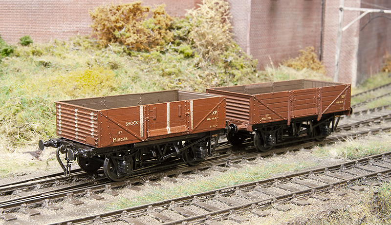 The finished wagon in the company of yet another D2150 13t open.
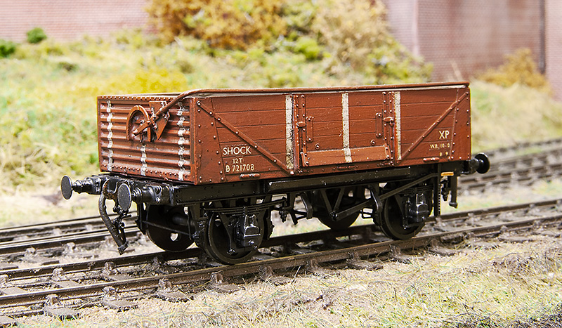 The BR wagon has had a Rumney models sheet rail added and been mated with a clasp brake chassis to produce a D1/040 variant. Buffers are from Lanarkshire Models.
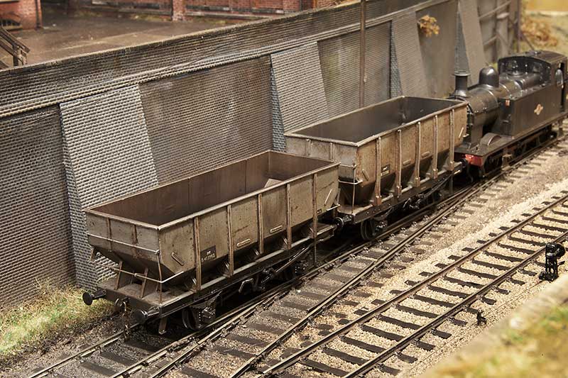
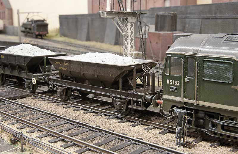
Moving on to a couple of hoppers. 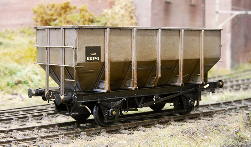 First up the Accurascale 24.5t hopper which i picked up cheaply from a private sale on Western Thunder. It came in brown livery and with a certificate saying it was a limited edition number 061 of 500. If this sort of thing matters to you and you have one you will be pleased to know that your model is now even more limited being 1 of 499 (You’re welcome!). It was separated into its component parts (a process that had already started in the box) and the body resprayed. These are not a straight drop in wheels job as the axles used are a little short and theres a boss on the back of the W-iron, much like Lima was doing 40+ years ago. Its not a huge problem though as a few turns of a bearing cutter (I use Ed’s tool) and a little bit of thinning the boss down and off you go. I also cut off the NM pockets.
What is a little bit more of an issue is it doesn’t weigh anything, just 21 grammes out of the box. Obviously if you plan to run your wagons loaded no problem but if you want them empty (as did ) then a little bit of trickery is required.
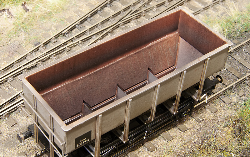 My solution was to make new lower sides from 1mm lead. This brings the wagon up to 50 grammes. If you would like to follow suit I drew up a little cutting template which you can download from here
 Another parkside 21 tonner based on a picture that came up on my facebook feed. (some of the wagons in the post are waiting a delivery of couplings you may notice). Theres often a discussion when these kits crop up that they are difficult to build but they really aren’t. The trick is to assemble a side and end as 2 pairs on a piece of glass with a cutting matt to ensure they are square, let these set fully before assembling the rest of the wagon and theres no problems Any slight gaps between the panels can be filled from the inside using Mr Surfacer 1000 liquid filler.
 Now a few oddballs – this is an ex L&Y diagram 81 loco coal wagon from the old MAJ models kit. The kit is supplied with a wooden chassis which is correct for the earlier wagons but i wanted the later one so only used the body. The brake gear on these were a little weird to say the least
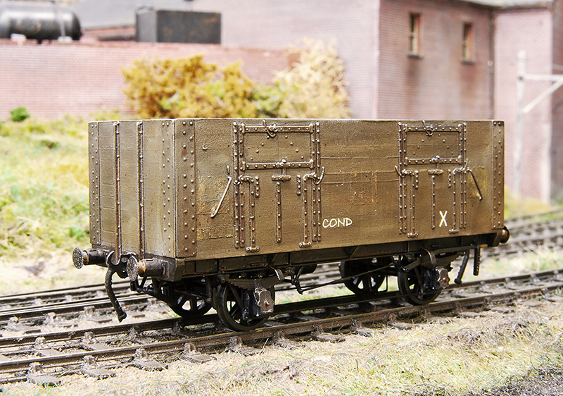 The plan is to have a short train of condemned wagons that is delivered to the yard as a trip working from Bescot. These are then to be collected by one of the Round Oak locos to be taken away for scrapping and the metal bits melted down in the furnaces. This is basically what happened and quite a few locos met their fate this way in real life. Unlike some of the more famous railway scrap yards stuff didn’t hand around for long so nothing from my scrap train will have any hope of reprieve sadly. The condemned markings are from Railtec,
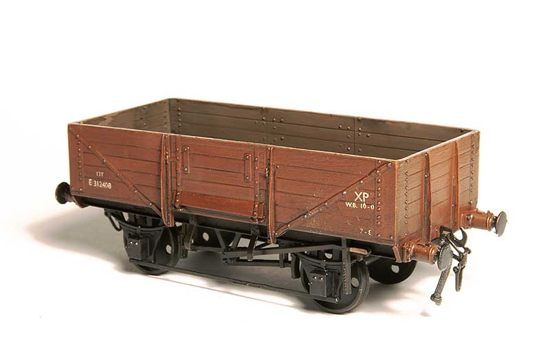
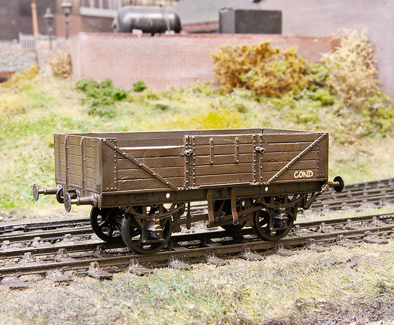 Another victim this time a GWR diagram 04 open from the cooper craft kit. Like another Coopercraft kit I’ve built this has the bearing holes mounted too low meaning that the wagon looked like it was on stilts. This one has slightly odd brake gear as well. You can just make out the old GW branding.
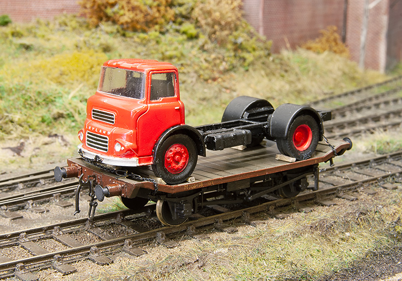 The LMS traction truck has finally been mated with its load.
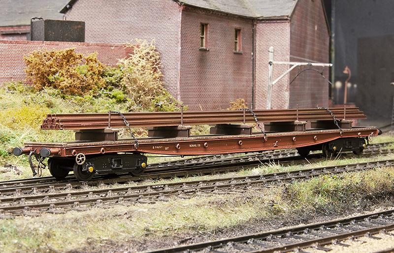 Also based on a picture that cropped upon my facebook feed is this Borail from the Cambrian kit. Making the load was far from the most interesting task I’ve ever done I can tell you and despite it being essentially hollow this wagon still hovered up 5 meters of rail!
Its all gone a bit Eastern Region
Over the last week or so Ive embarked on another test build for Brassmasters. This time a J17 kit thats been designed by David Barham. Its not really any use for Brettell Road but it would fit North Elmham (which I have been know to help out with).
The basic chassis build with a High level Loadhauler gearbox. The loco and tender use CSBs throughout. The kit will be supplied with both printed and etched brake shoes.
 The tender subframe – Again with options on the brake shoes.
 Chassis and footplate.
 Tender with its outer frame.
 The cab
 Pretty much everything above the footplate and forward of the cab is catered for by a 3D print. Here I’ve made a start on the basic detailing
 The tender body, like the loco, is a 3D print.
The detailed up chassis
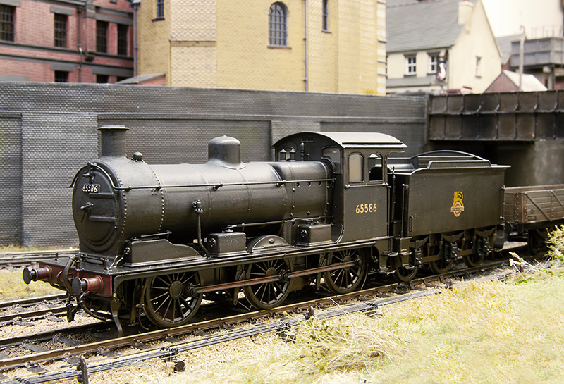
The finished loco – More pictures below. This has been a pleasure to put together.
Clay and sheets
One working that passed through the real Brettell Lane and kind of fascinated me was the St Blazey to Etruria china clay working. This service ran for years and was somewhat erratic in the paths it took. Usually going via Worcester, Stourbrige then Dudley before heading off to Bescot. Or it could go right at Stourbridge via Old Hill and (I think) Soho Junction. These routes avoided the Lickey but I’ve seen pictures of it going that way too in later years. When I was at University in Stoke it would often turn up at lunch time behind a pair of class 37s although it did switch to a class 60 in the time I was there.
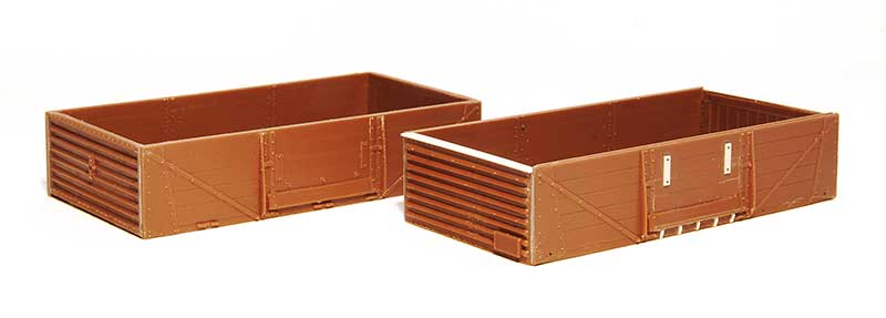
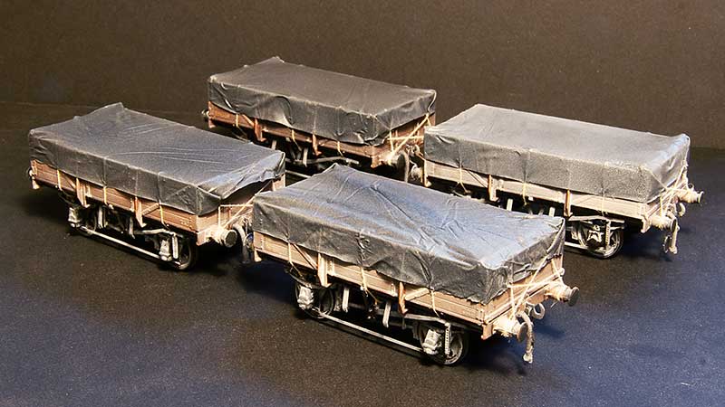
So to have a clay train on Brettell road makes sense as a through service. I like the classic diagram 1/051 clay opens with their sort of cute, baby open wagon look about them. A little bit of rewriting of history is needed though as they tended to stay in Cornwall and not venture out to the Midlands. Brettell Road is set before the introduction of the clayliner service so my justification is that BR was trialing things out to see how they would work and thats good enough for me.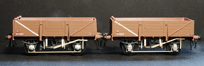
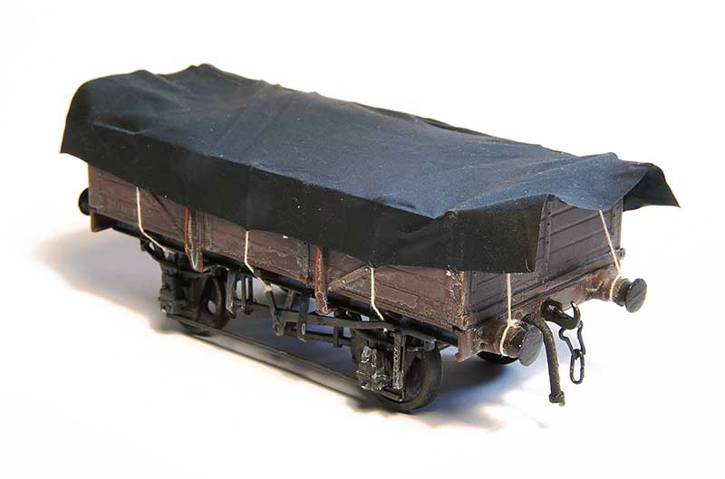
Ratio make a nice little kit for these and I was fortunate to find someone selling a box of 7 on Ebay for what basically worked out as a fiver each. The bodies go together well with a little bit of modification to make the ends fit. The kit features a somewhat crude attempt at a roller bearing and the brake levers are quite poor. It also includes cast buffers that aren’t all that great. So the bearings were replaced with MJT ones although my research showed oil axleboxes to be more common anyway. Brake levers are from the Mainly Trains etch, door bangers from Rumney models and buffers from Lanarkshire models. I did one as a test then built the other 6 as a batch.
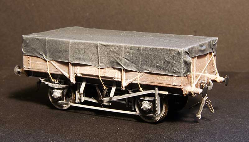
Before I move onto the sheets a bit about the weathering. I followed my usual approach of a wash of dark grime followed by a spray of AK interactive dark mud. This was then all sealed with Klear before AK interactive white ink was used (in various levels of dilution) to give an overall effect of clay staining. You don’t want a fully weathered wagon at this stage, try to think of it as you are aiming for about half the effect you ultimately want.
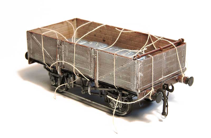
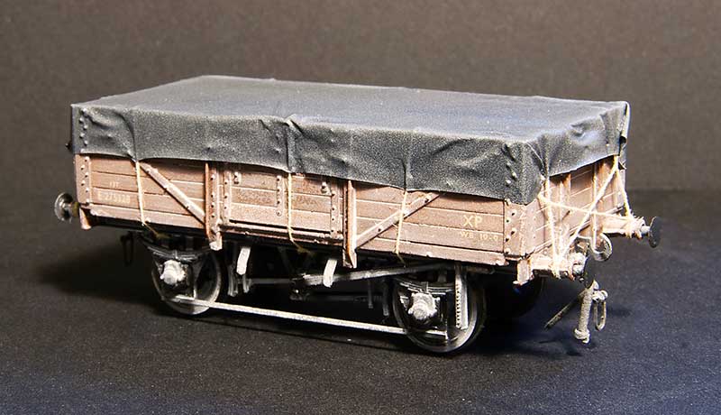
Previously when I have done wagon sheets I make the sheet up with the ropes attached to it and then attach it to the wagon. This is a bit of a faff and sometimes the glue holding the rope to the sheet can give an odd effect so I approached this a bit differently. Roping of wagon sheets is a whole topic on its own and I will leave that too someone who has properly studied the subject but I just looked at pictures and coped what I saw. So the first stage is to attach the ropes (cotton) to the wagon – Tying it on at the visible ends and gluing to the wagon top with Loctite
 This was then tided up by first sealing the knots with Zap Pink superglue. Theres no huge reason to trim the ropes inside the wagon but it pays to just keep things neat so they don’t get in the way later.
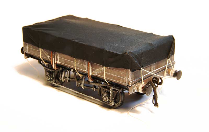
As mentioned before the sheet is made from black latex gloves (actually nitrile) and mine are a brand called Supertouch. They are a bit awkward to cut as the material tends to snag on the scalpel blade even if the blade is brand new. A method I found to work best is to stretch the glove over a bit of cardboard, make a template and to cut it using the handle end of the blade not the pointy end, pushing the scalpel away from you to cut. I don’t know why this makes a difference but it does! As i’ve mentioned in the past the material is black on the outside and a dark grey on the inside. I use the black side as its depicting wet conditions but the grey is good for a nice sunny day layout.
The sheet is then positioned in place, not forgetting to add weight inside the wagon and bulking it up with a bit of tissue first before gluing to the wagon tops in 6 places, about where the ropes are. Use Loctite and start in the middle (it sets very quickly) and remember to pull it taught as you glue the outer sides. This is one of those things were you probably need a bit of variation but you don’t want to force it. I find if I try to be as neat as I can, I’m not all that neat really and I get the variation by default.
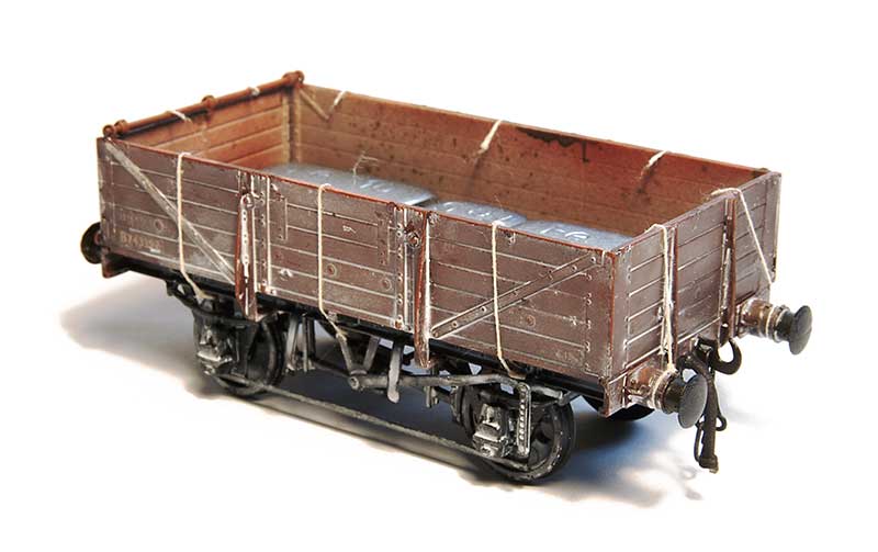
Next stage is to glue the sides of the sheet to the ropes, again with loctite and again puling the sheet taught. I found holding it in place for 10 seconds was all you need. It pays to glue the sheet the side of the wagon at the ends at this stage
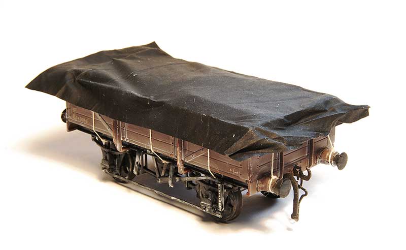
On to the ends. Another drop of super glue on the top and the sheet can be glued in place. The corners can be folded and secured in place and the last set of ropes glued into the sheet itself. 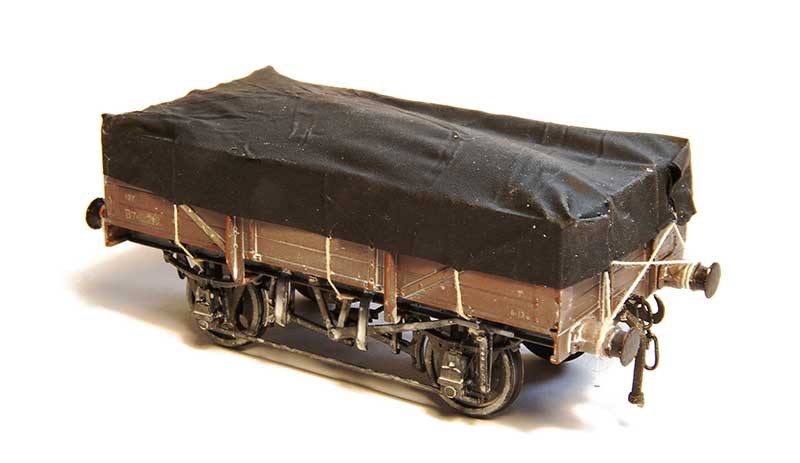
The last ropes tied into place and tidied up.
The final weathering, back to the white ink (sprayed this time) with some additional grease stains on the underframe.
 To break up the rake a bit I added a few 10ft wheelbase opens too. These are actually way more typical of the actual wagons used in the clayliners. The ex LMS Diagram 2150 I’ve featured before a few posts ago.
Likewise the ex LNE diagram 210 (although not this specific model)
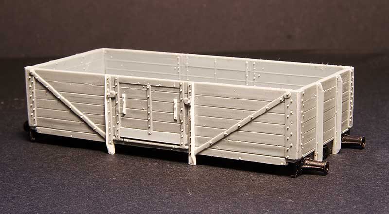
A new wagon type for me is the ex LNE diagram 185. This was constructed from the body of the Cambrian kit C81 for the LNER 12ton 6 plank Open Wagon, With a Parkside 10ft underframe. Theres a few tweaks needed to the body as can be seen and theres an additional top support across the top of the door which is worth adding assuming you aren’t going to cover it over with a sheet that is!
Just need an enterprising transfer manufacturer to produce some sheet markings now.
More shockingly mundane stuff
As a follow on to the last post – more every-day wagons have rolled off the workbench. This time it’s a quartet of shock wagons.
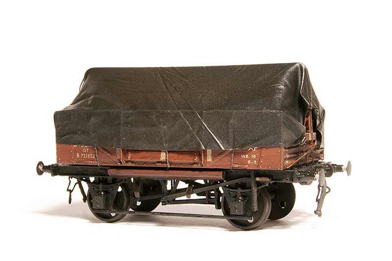
Starting with the basics – Diagram 1/040 shock open from the Parkside kit. Built pretty much as supplied with the addition of a Rumney Models tarpaulin bar and a sheet from my now standard black latex glove.
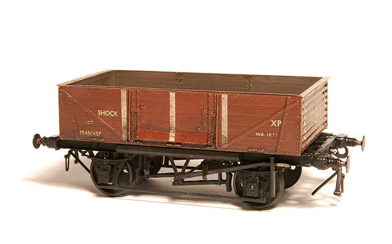
Next ex LMS diagram 1983 from the same kit as above with the additional top lip on the ends and buffers from Lanarkshire models. You cant see it in the pic but I replaced the floor with scribed lead sheet.
EDIT – More info has come to light on these wagons and this one is wrong – see https://p4newstreet.com/back-to-wagons-and-a-correction/
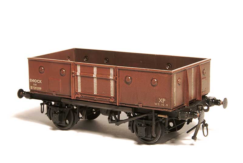
A smidge more involved is this Diagram 1/038 shock open from the parkside kit for the standard (not shock) wagon. I shortened the sides by cutting sections out next to the middle section and mounted them on a new floor as the prototype wagons had a visible lip around the bottom.
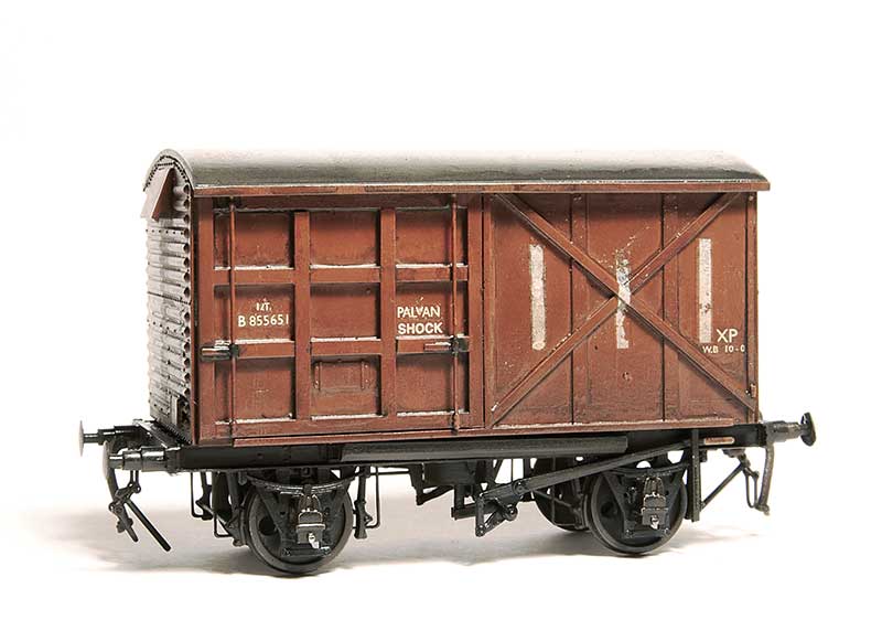
Finally a diagram 1/219 shock palvan. A bit more involved again as I could use spare ends and a roof from Parkside standard 12t vans but the sides needed to be made from scratch. The chassis is the Red Panda kit.
Just some mundane stuff.
Just one of those every day, run of the mill style posts this time but with a few little tweaks to appease the wagon buffs.
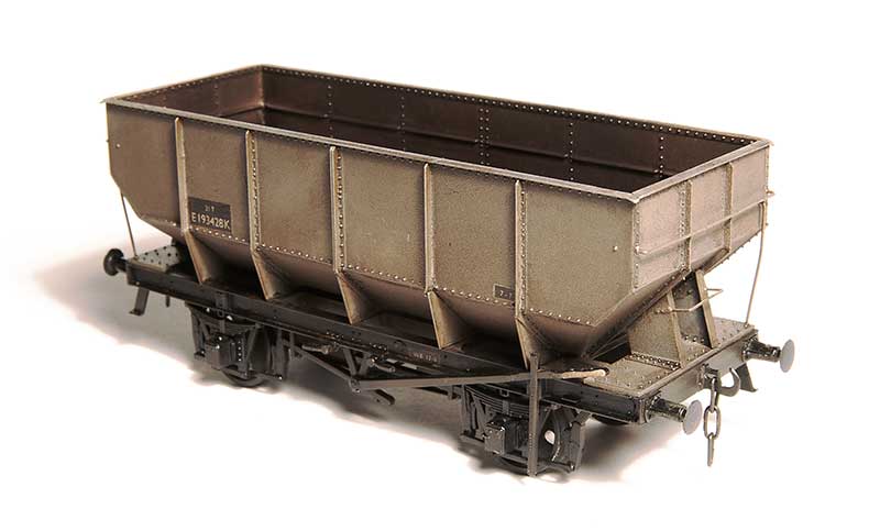
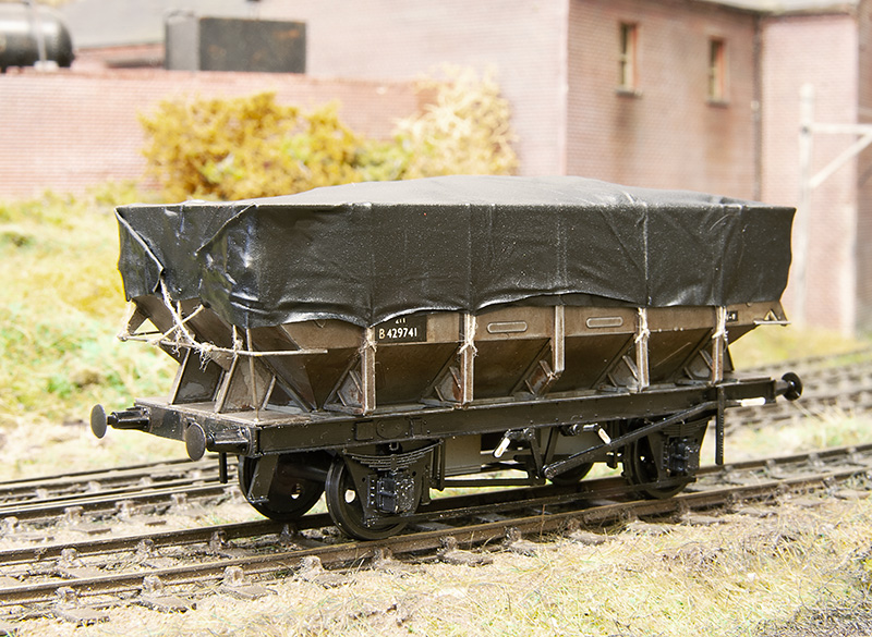
Starting with the Parkside kit for the LNER 21t riveted coal hopper. Built pretty much as instructed but I did change the side stanchion plates for 10 thou plasticard as the ones in the kit were a bit chunky.
 The spare brakes that came with the above kit were used to correct the brakes on my prototype 24.5t hopper I’ve featured before.

The humble D2150 13t open from the Parkside kit. The only real visual difference between these and the BR build is the small lip on the ends. A bit of 10×20 thou mictrostrip sorted that.
Ex LNER Diagram 210 adapted from the parkside kit for the Dia 1/120 wagon. The side stanchion were slightly reshaped as were the buffer beams while the chassis was replaced with spares from my scrap box.
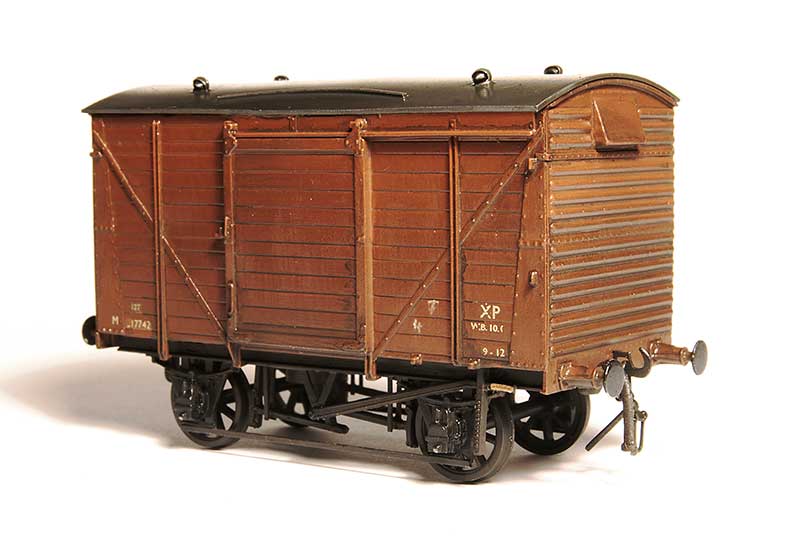
Another bog standard affair, the D2039 ex LMS 12t van. This one was built from the Ratio kit with the addiction of the Rumney Models LMS van detailing etch (B105). It features the 3 part end for a super subtle bit of variety.
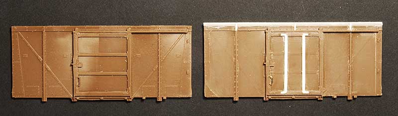
Finally something a little more involved. Before and after of the sides for a D2103 12t van using the parkside fruit van as a start point. The ends were scratchbuilt.
Back to business as usual
So back to business as usual then.
This is an ex LMS 12 ton traction truck which has recently been released by 247 Developments. The kit is a 3d print which is supplied as a body with solebars, W irons, brake gear and white metal buffers. The body was a little bit distorted (kinda like a spoon shape) but popping it in very hot water and weighting it while it cooled seemed to take most of the distortion out. The back of the frames needed thinning for p4 wheels to fit (I believe the kit has been changed to rectify this now). I replaced the sides with microstrip as they were a little uneven and added the safety loops and tie down shackles that were missing from the print. The supplied buffers were a little odd so these are Accurascale ones. Just need to do a load for it now.
 On Brettell Road I have mostly used cast white metal vacuum pipes. Generally these have been fine but I have had some of the bufferbeam mounted ones break as they are slightly vulnerable. David Roome has now produced some 3d printed ones that are rubbery and a lot less susceptible to knocks. Im not replacing them on all of my wagons just as and when a white metal one gets broken.
Links
Test prints
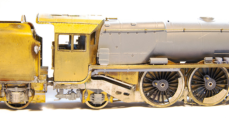
Progress on the Princess Coronation build continues with some test 3d prints for some of the details. These are only testing out ideas at this stage.
Above we see the bogie bearing pads and bracket, cylinder fronts, Ejector and brakes.
I admit that i had quite a wow! moment when I first saw the ejector. We are exploring the idea of 3d prints for the brake shoes as it allows you to position them closer to the wheels without risking a short. Where the front one squeezes in between the front driving wheel and the rear bogie wheel seems particularly advantageous.
 Pony truck axlebox and springs along with some of the under cab pipework. One of the small AWS cylinders can be seen on the footplate
More AWS bits – this time on the firemans side. The roof is still a loose fit at this stage.
State of play so far.
Heavyweights done
Just a super short post this time. The wagons featured last time are done and can be released into the wild.

Is it just me or do metal kits always just seem a bit ‘meh’ once they are painted?
A couple of WIP heavyweights and breaking the golden rule.
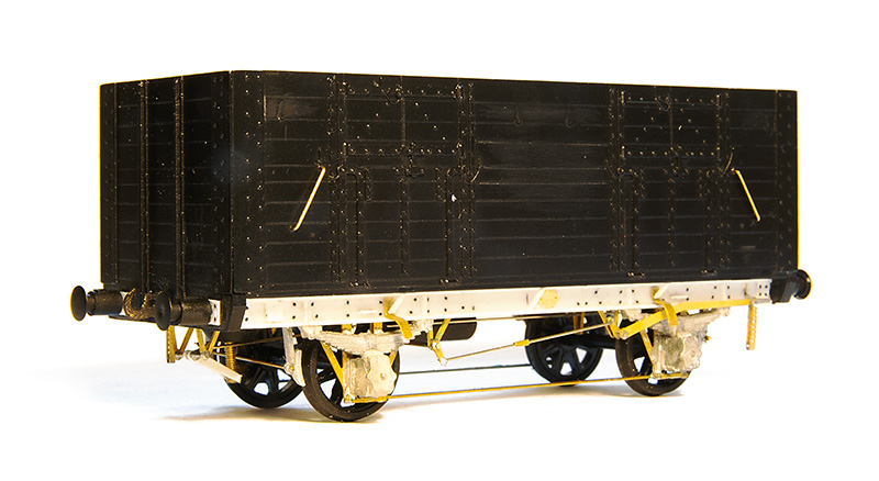
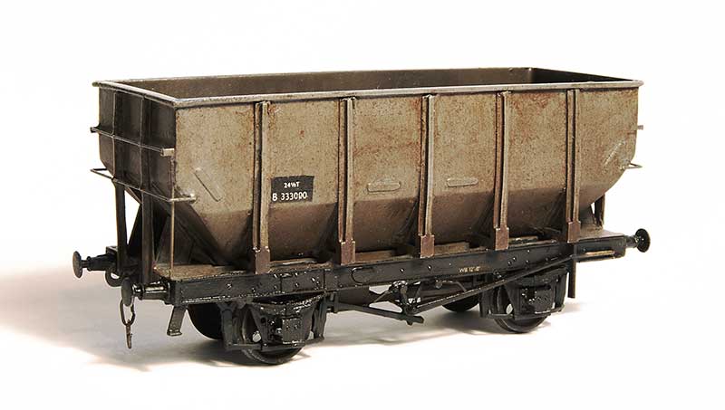
When my friend Tom kindly gave me the Ks kit for the Coral glass wagon (featured earlier) he also gave me another Ks kit for the 24.5t coal hopper. Further investigation showed that this was a kit that was based on the prototype B333000 which was not really like the production ones in that the ends were different. I suppose back in the day this was your only option however now you can buy 24.5t hoppers ready to run this strange little oddity might have a little value as something different from what everyone else is doing.
B333000 was one of 2 prototypes and was built at Shildon. The other B333001 was built at Ashford and it seems to heave been this latter example that influenced the production run. I believe B333000 was later used for experimentation of the automated doors used for MGR trains but photos of it are rare as hens teeth. Simon Bendall kindly supplied the only picture I had to work from.
So, breaking a golden rule I have had to make educated guesses about some of the details of this wagon. The underframe in Simons picture is very dark and looked to have been modified in some way. It was claimed the Shildon design was basically a taller 21 ton hopper and the lack of outer discharge doors kind of backs that up. So getting hold of a parkside 21t kit to use as a guide I set to work.
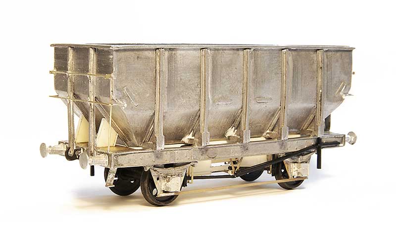
The hopper had some chunky mouldings on the inside of the corners that gave quite a positive location. But as I wanted it to be empty they had to go. I replaced the W Irons with Bill Bedford sprung ones (from my nearly depleted stocks) and Wizard model axle boxes. These were soldered in place as supplied and when I was happy everything was square the centre of the w irons was cut away to give an open floor. The end platforms were replaced with a bit of brass as the moulded ones sat on top of the solebars and were too thick. The kit had no hopper doors so these were made from plasticard using a parkside 21t hopper kit as a guide.
The finished wagon (well almost finished – I haven’t added the door mechanism handles yet) is a bit of a heavyweight in that its 78 grammes. About 50% more than my usual target of 50g.
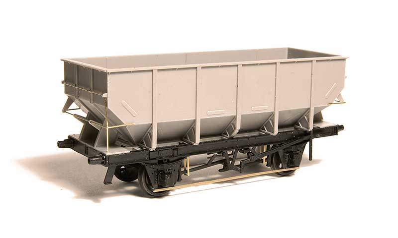
The parkside kit built up. This is the opposite of the Ks kit as while i added some lead overlays to the inside lower hopper its a tad light at only 38g.
Moving away from hoppers I’ve also finished of the construction phase of this…
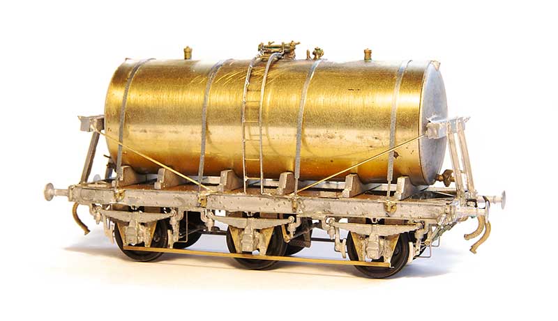
A David Geen milk tank which I was told by the man himself when I brought it was the last one! This uses a Rumney models chassis and has, to be honest, been a bit of slow burner. Its one of those kits that I just seemed to struggle to get any enthusiasm for but I’m pleased with it now it’s done. I thought the hopper was heavy but this weighs in at 88 grammes!
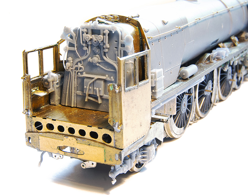
Duchess update – Starting to look like a loco now.
Footplate with mounting bolts and Splashers in place and tided up ready for separating from the jig.
 But before I can do that need to fit the cab, firebox, boiler and smoke box so that theres something to give it a degree of rigidity. This is the basic cab assembly.
 And inside mounted to the footplate. The seats are posable!
The cab roof. This builds up on its own mini jig too.
Underside from the front end.
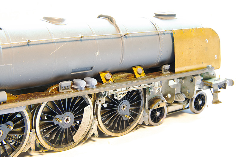
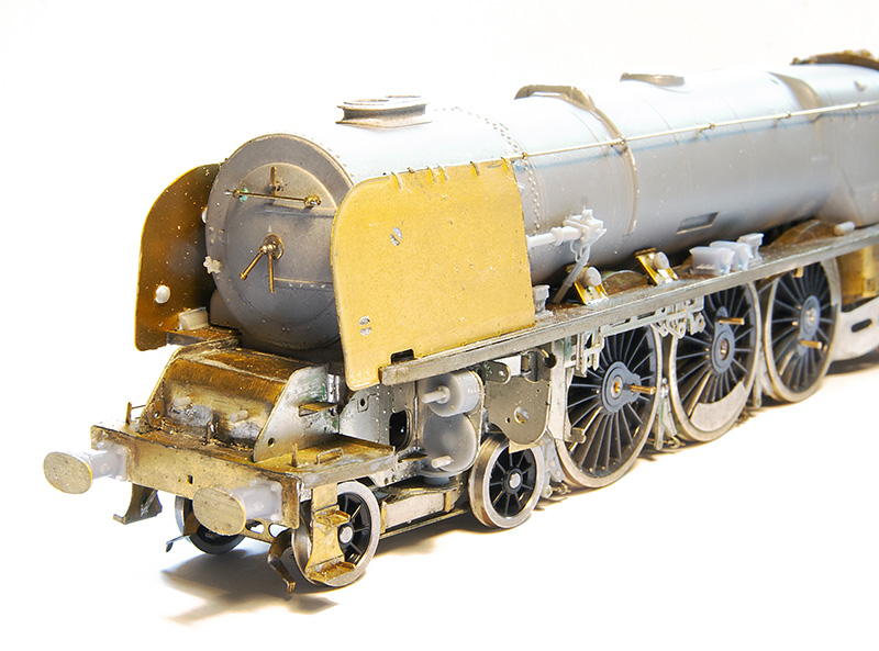
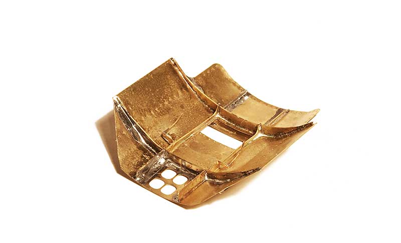
The main super structure comes in 3 parts cast in resin. The firebox and boiler. The smokebox saddle and the smoke box. There are 3 types. A round single chimney. The flattened top double chimney from the ex streamlined locos and a round double chimney as seen here.
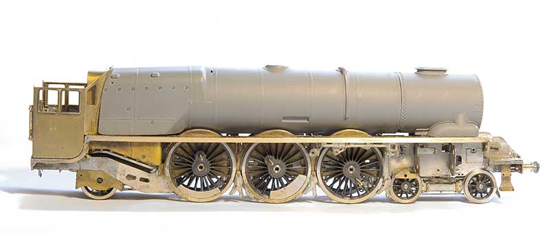
The body removed from the jig, tidied up and fitted to the chassis.
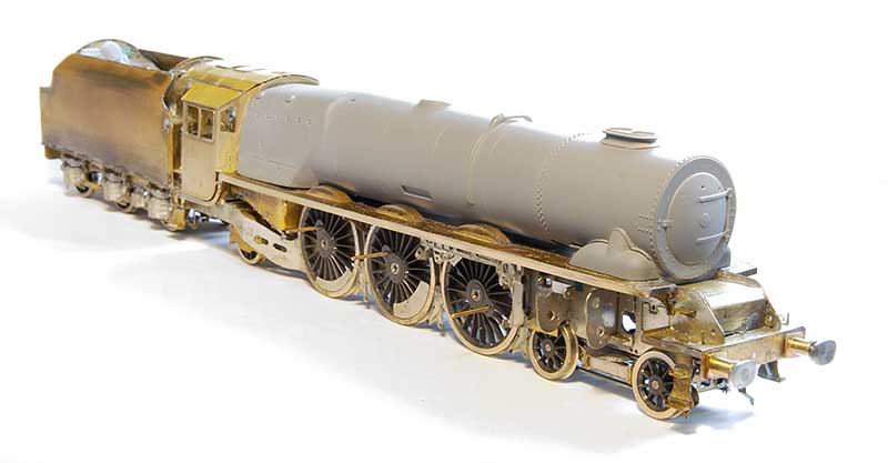 Finally – I couldn’t resist!
Steel and Glass
Let’s talk about glass. Something Stourbridge is particularly renowned for. It is believed that there has been glass production in the area for hundreds of years with a factory opening at the lower end of what is now Brettell Lane in the 1640s and production continuing in the area ever since.
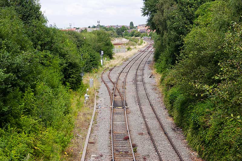 You’re going to need your imagination for this bit! Regular readers will know that Brettell Road is not an accurate model of the real Brettell lane but is inspired by it and the local area. The above picture taken in August 2014 (that long already?) shows what was left of the goods yard at Moor Lane. Brettell Lane is behind us. The line to Pensnett branched off on the left and the yard is petty much straight ahead of us. You can see the flood lights against the skyline. This was the view from the left hand end of the original version of Brettell Road and is now the view from the middle looking to the right. On the model the line is not an S curve but a continuous left hand bend. Also the main line descends from this point on the layout while the real line rises as it goes away from us.
On the right, long gone now, there used to be a siding which served the Brierley Hill glassworks. The buildings are still there and can just be seen behind the trees in the distance where the mainline disappears.
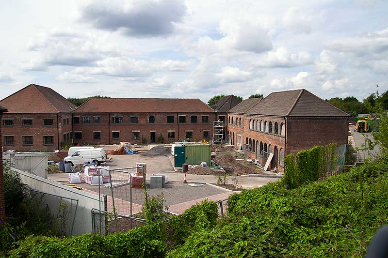 Another view from 2014 that shows the building being converted into apartments. If you stand looking at the right hand end of the layout you would effectively be standing in this building. The line runs behind it and you can just make out the ironwork of Moor Lane Bridge on the right of the picture above the yellow van. This building is represented on the layout as part of the backscene.
Brierley Hill glass was more of the decorative, cut glass and crystal type than the industrial large sheets and I have a few shockvans as a nod to glass traffic but of course they could be carrying anything so only I know that. However thanks to a gift from my friend Tom i now have something a little more obvious…
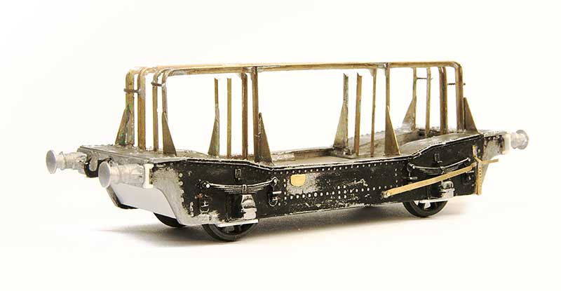 I present you the ancient K’s kit for the GWR Coral glass wagon. These were built in 1908, to 2 diagrams, by Swindon to carry large plate glass in crates. BR briefly continued with these building 6 more examples before switching to the LMS design but even then only building 42 wagons (also at Swindon).
I decided to build one of the BR types with the main differences being (as far as i can tell) the shape of the ends of the frames, the GWR ones being more curvy, and the brake levers. The model had been started by Tom’s dad but was dunked in some cellulose thinners which dissolved the glue (but not the paint strangely) before it was reassembled using low melt solder. The kit had some nice brass buffers which were replaced with Lanarkshire models which better match the BR examples. The upper frames were cast in whitemetal and there were only 2 of them so they were replaced with brass section. A part of the original casting was soldered to the end of the underframe and reshaped to better match the BR design. I used the slotted bearing and central pivot method of compensation as previously used on my lowmac. 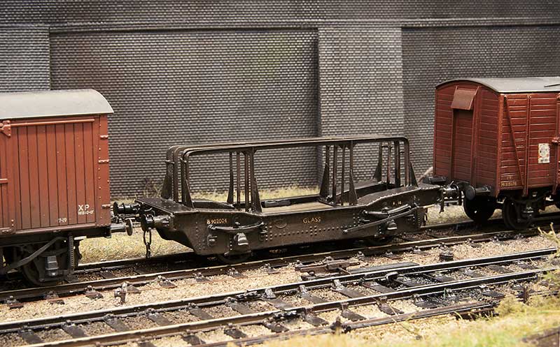 In service on the layout. As mentioned its not really the sort of glass that Brierley Hill was known for but it is a nod to the industry. Apparently some of the real wagons were transferred to the steel industry anyway so perhaps its on trial in the area for that reason instead?
Thanks go to Tom and his dad.
A couple of classics
This time we have a couple of classics from the Cambrian range
 The good old catfish. Built with the use of Stenson models hand wheels and replacement handrails. One thing with these, as supplied, is that the wheels seem a long way away from the w W-irons, even in P4 so I cut the moulded rings off the back and moved the solebars closer together. A lot of people say these are a bit tricky but the only real difference to any other kit is you just need to take a lot longer and really let things set. They aren’t really a bung it together in an afternoon style job. I found another 2 kits in my stash which i will build up for New Street and might do a bit of a step by step on how to do them.
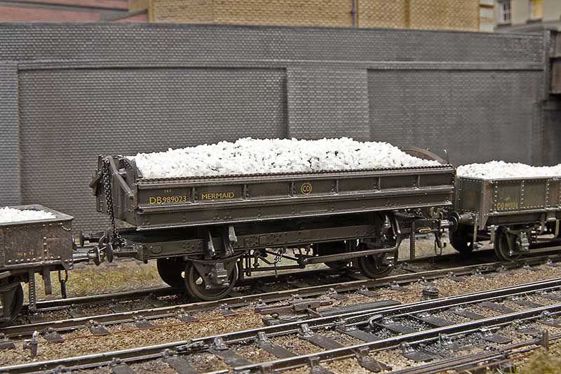 Next up the mermaid. I have built this as an early one which were the same as the original GWR builds. The main difference is push rod brakes instead of clasp, no vacuum brakes and earlier buffers. The rail clamps were replaced with Roxey mouldings shackles.
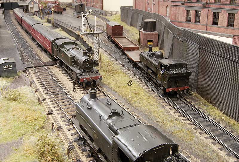
Below – It seems Brettell Road has had something of a GWR take over today!
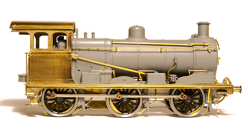
An unremarkable little tank engine – Part 1
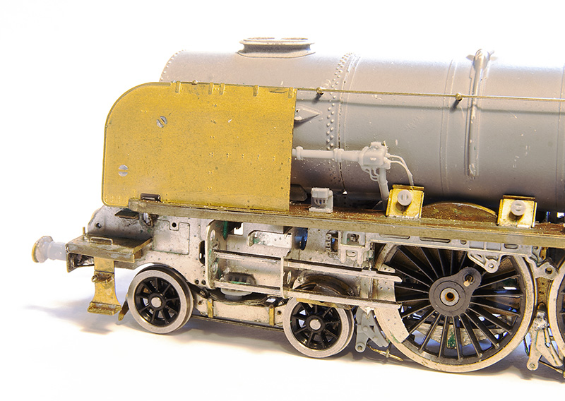
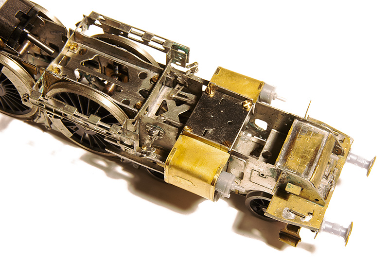
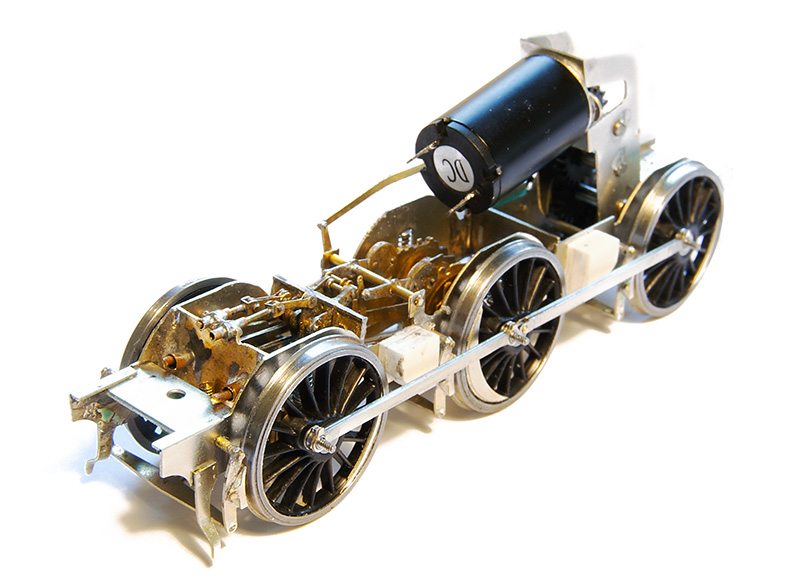
One of my slow burning projects has been a humble little 57xx tank. A combination of the old (But essentially quite good) Mainline body and a High Level Kits chassis but with a bit of twist.
Iain Rice wrote about these back in MRJ 61 and 62 using a similar route, in his case using a Perseverance chassis as that was what was available around the time, and I would urge readers to refer to this as a start point.
The High Level chassis
 Like all of Chris’ chassis this was a joy to build (this is my 4th of his chassis kits now, who would have thought it?) I opted to use Brassmasters bearings which may have messed the alignment up a little as I found I needed to mount the break gear 1 mm lower than as supplied. Strangely though the buffer height seems fine. I differed a little bit from the instructions by making all of the brake gear removable. The rear rods that go behind the wheels seems to trap the rear axle in place as supplied.
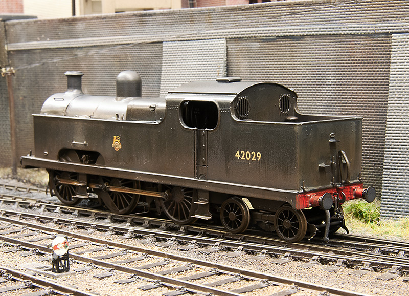
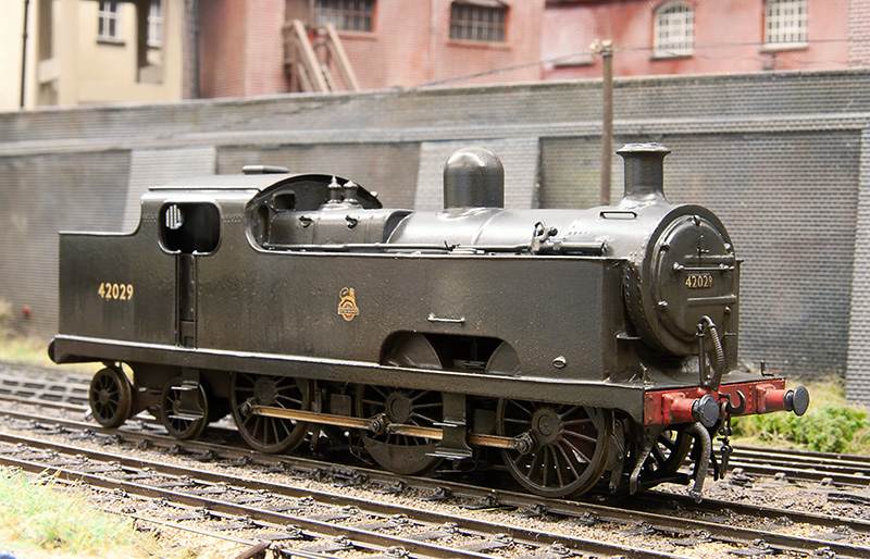
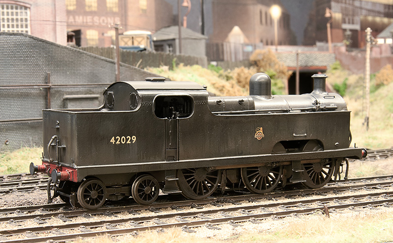
Eagle eyed viewers might spot something little odd and yes, you’ve guessed it – I’ve gone off piste again.
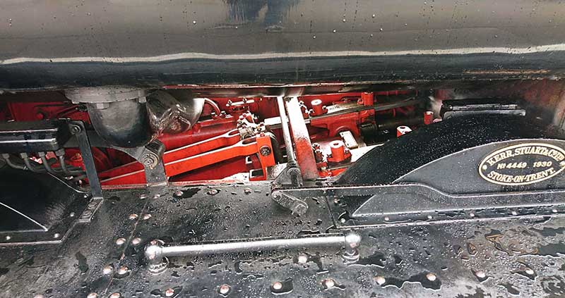
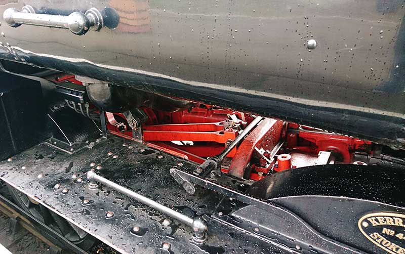 A couple of prototype pics from the Severn Valley. Personally i though the inside motion was pretty obvious looking at the real thing and while there is a representation of it in the High Level Kit I wanted it to move.
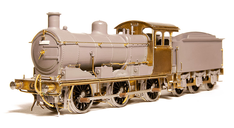
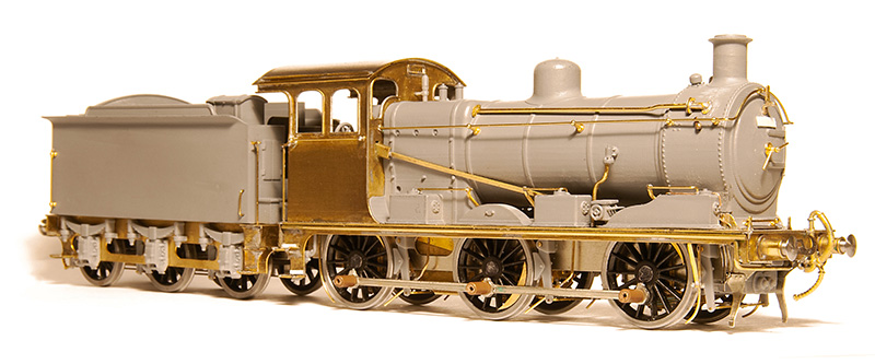
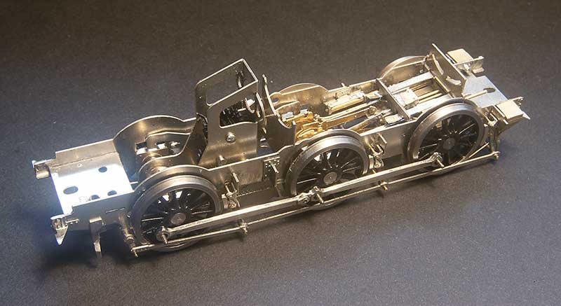 So this is a mish mash of bits – Brassmasters 4f bits at the axle end and Finney GW bits at the front. The GWR version of inside motion seems much simpler that the midland one and the hardest part of this task wasn’t putting it all together but getting it in place. Being a small loco theres not a huge amount of wiggle room.
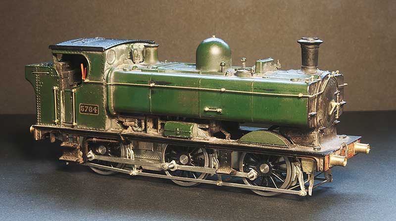
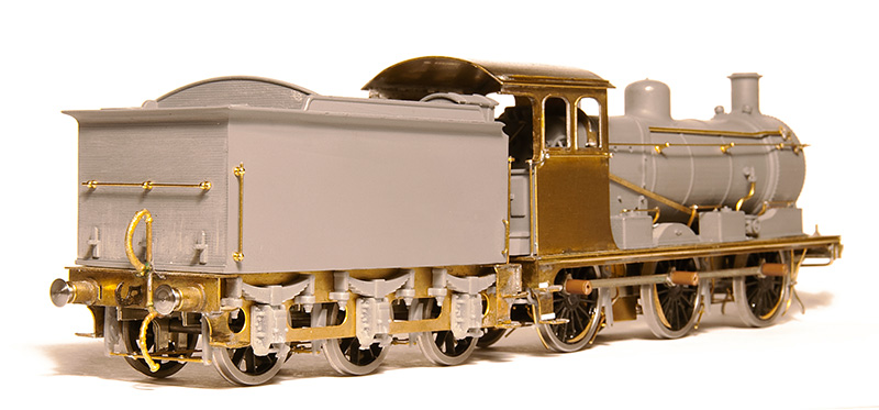
The body is essentially good, you could say extremely good for its time. The obvious stand out bit of weirdness was the top of the dome but nothing a spot of filing can’t sort out. It did come with a separate main handrail and some wire ones around the bunker but they were all a bit heavy so i replaced those along with those handrails that were moulded on. I reduced the size of the front wheel splasher by cutting it off and gluing it back on, The width of the cut being all you really need. I didn’t feel the need to fiddle with the centre and rear ones. While on my 94xx I replaced all the pipework under the tanks in front of the cab with this model I thought it was good enough as is, although I have cut away the ‘holes’ as per Iain’s article. Theres a bit more detailing to add to the footplate yet and the lower pipework will need to be replaced.